Solar distribution within rooms (facilities)
In ESP-r the patterns of direct sun patches within rooms are part of the energy balance of surfaces at each timestep. After the first point of intersection for direct solar radiation subsequent reflections are treated as diffuse. An iterative method is used with up to 10 iterations.
Direct and diffuse radiation are considered evenly distributed across surfaces, surface temperatures are considered uniform across each face of a surface. One approach to higher resolution is to increase the number of surfaces - e.g. split the floor of the zone into multiple surfaces to reflect regions which will and will not be directly insolated.
Radiation passing through a transparent partitions is considered diffuse and is applied to the adjacent zone at the next timestep.
In ESP-r users, can if they wish, define interior reveals (at framing and walls) as separate surfaces to closely match actual coordinates. These will participate in the insolation analysis. The more common approach is to treat facades as geometrically flat.
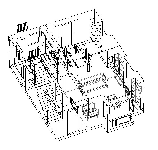
Where furniture and fittings need to be represented users can make use of a range of pre-defined objects which include both visual and thermal attributes. Visual attributes include a range of primitive rectilinear shapes which are included in wire-frame and Radiance renderings. The thermal attributes include one or more pairs of surfaces which take part in short and long-wave radiation and convective exchanges within the zone. The image below is a residential model which has been populated with a number of pre-defined entities (see databases).
 see full size
Solar distribution within rooms (implementation)
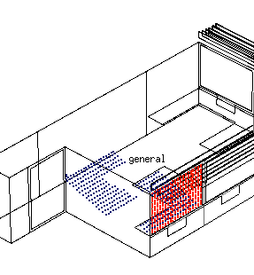
In ESP-r insolation calculations are carried out by the ish utility module. Insolation sources (glazing) and zone surfaces are gridded. Each insolation grid source projects a ray at the current solar vector and intersections are tested. A large source surface might insolate several zone surfaces. In the figure below the red dots are the grid placed on the insolation source and the blue dots are the points of intersection within the room at a point in time. What gets saved to the shading and insolation file for each zone is the percentage distribution from each insolation source to receiving surfaces.
The following directives are available to control insolation calculations:
The computational burden of insolation calculations can be adjusted by increasing or decreasing the grid density as well as restricting the months that are pre-calculated. For zones which include surfaces with small dimensions (a thin frame) it may be necessary to increase the grid resolution.
The ish module has options to view insolation patterns within rooms.
Insolation distributions for each insolation source are recorded to an binary files (there is an ASCII equivalent) as a list of insolated surfaces and the percentage of the transmitted direct solar radiation for each insolated surface.
Distributions are accessed from the simulation engine via reading a binary file of shading and insolation data.
Back to top | Back to Welcome page