Electrical power distribution
An electrical power distribution data model and solver were incorporated into ESP-r in 1994 and this has evolved over time.
Network definition
Electrical distribution is represented as a series of interconnected nodes where each node represents an electrical bus bar at which conductors, loads and generation sources connect. At each node, power is either generated, absorbed by a load or transmitted. Power carrying components such as transmission lines and transformers are represented by admittance (the inverse of complex impedance). Models exist to determine PV module and generator power output as the solution progresses. The purpose of the solution technique is to determine the node voltage and phase angles, the real and reactive power flow between nodes as well as the system transmission losses. The solution also reveals the power requirements/surplus for import/export in a grid connected system.
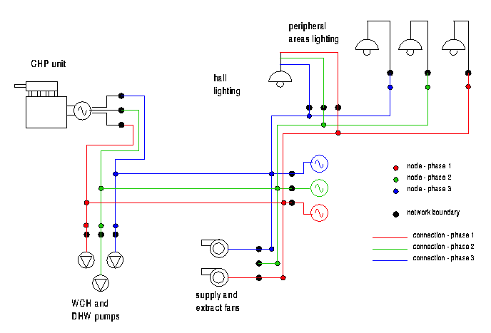
In general the thermal model describes the loads (lighting, small power, environmental control equipment) which are solved within the electrical domain. This integrated approach allows explicit simulation of combined heat and power and hybrid renewable energy and grid schemes. In the figure below a CHP unit is used in a distribution system which includes environmental systems components as well as lighting.
Numerical approach
The power flow solution technique is topologically similar to that used to solve mass flow. Just as a mass flow network can include paths for air and water flow there are both DC and AC current to be resolved in power flow simulation. Currently two solution routes are available: the default Newton-Raphson solution and the simpler but slower Gauss-Siedel solution (used mainly as a reference solver).
Back to top | Back to Welcome page