|
Fuel Cell Reformers
Reforming of Biogas Feed for Fuel
Cells
Introduction In considering the use of fuel cells with biofuels as the
primary fuel, a means of recovering hydrogen gas from this feed is required. The
technique used with biogas feed is that of reforming. Here, either a feed gas is reacted
with steam at around 800oC in the presence of a catalyst, which
results in a gas mixture containing hydrogen and carbon dioxide, or internal reforming occurs.
In the case of high temperature fuel cells such as SOFC's, there is high grade waste heat which can be used to facilitate internal reforming. In lower temperature fuel cells such as the PEM and PAFC types, the waste heat is low grade and external reforming is required. There are several types of external reformer available or being developed, these include-
The different types offer different characteristics and may be chosen to suit the fuel cell type, fuel supply or load characteristics. A review of the principles of operation of these reformer types can be found in reference 1 below. |
Index of technical reviews |
Prior to feeding the biogas to the reformer, sulphur species must be removed from the gas. All sulphur species are poisonous for catalytic processes employing reduced metals or metal oxides as the primary active phase, therefore a desulphuriser is employed. Here the sulphur compounds are reacted with hydrogen to produce hydrogen sulphide. The hydrogen sulphide is then reacted with zinc oxide to produce zinc sulphide and water. This process is known as chemisorption and may also be carried out using iron oxide. The treated gas is then passed to the reformer.
In the case of the PEM fuel cell even trace amounts of CO are poisonous to the electrocatalysts in the anode. Therefore, for such a cell the hydrogen must be separated from the CO and cooled.
The Reforming Reactions
In the case of pretreated biogas, we are interested in the methane reforming reaction which
takes place. Chemically the reaction is described as follows-
CH4 + H2O = CO + 3H2
CO + H2O = CO2 + H2 (this is the water gas shift reaction)
This gives the overall methane reforming reaction
CH4 + + 2H2O = CO2 + 4H2
The overall process is endothermic and requires an external heat input. Excess steam and heat is required to shift the water-gas reaction equilibrium to the right and maximise the hydrogen to methane yield.
The reforming reaction is achieved in external reformers by preheating the feed gas in a heat exchanger and reacting with steam at around 800oC in the presence of a nickel catalyst.
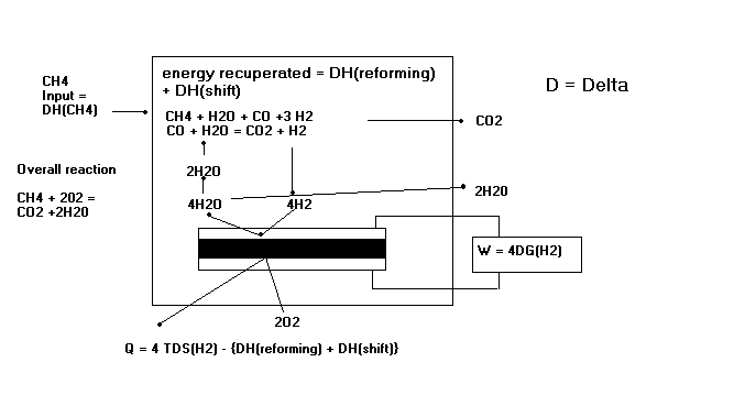
Reference 2 demonstrates the case of internal reforming in a SOFC.

The above figure demonstrates the process of internal reforming in a solid oxide fuel cell. Note the work and heat output equations, where the remaining heat after reforming is shown.
Internal reforming can be considered to occur in two ways:
- Indirect internal reforming
- Direct internal reforming
In the latter, the reforming reaction occurs in the anode fuel channels alongside the fuel cell
reaction. In theory, the removal of hydrogen by the fuel cell reaction helps shift the reforming reaction
to the right, but in practice indirect internal reforming predominates as all the methane is
converted to hydrogen close to the inlet of the fuel cell.
The reformer efficiency is conventionally expressed as:
n ref = heating value of products/heating value of reactants
However, to model the electricity and heat output of a fuel cell system it is required to separate the electicity and heat effects.
Electricty efficiency factor
The electricity generated by a fuel cell is a function of the quantity of hydrogen input. Hence the reforming factor in electricity generation is given by:
Eref = Actual yield of hydrogen from reforming/Theoretical yield of hydrogen from reforming if all fuel input was converted
The difference between the actual yield and full conversion will be due to:
- The equilibrium position of the reforming reaction (not being fully to the right)
- Any fuel combusted at the inlet to the reformer to provide preheating for the reforming reaction
Heat efficiency factors
For external reformers the following considerations apply:
- Heat and/or steam may be supplied from the fuel cell and/or from a preheater. As stated above, preheating will be required with low temperature fuel cells to achieve the required temperature
- Excess heat may be supplied in addition to that required by the enthalpy of the reforming reaction, to shift the reaction equilibrium to the right
- The fuel output from the reformer is cooled prior to entry to a low temperature fuel cell
With internal reforming for SOFC types, the excess heat supplied for the reforming reaction is contained within the fuel cell and should be recovered with the surplus heat from the fuel cell reaction, so the overall heat balance is valid.
- Dicks, Andrew L, Hydrogen generation from natural gas for the fuel cell
systems of tomorrow,Journal of Power Sources 61 (1996) 113- 124, Elsevier
1996,
- Gardener,F J,Thermodynamic processes in solid oxide and other fuel cells, Proc Instn Mech Engrs Vol211 Part A 1997,
