|
Fuel Cell Construction and Performance Characterisation This page describes how the internal construction and fluid flows
within a fuel cell
effects it's performance, the voltage-current output
characteristic and the efficiency. Implications for
the fuel flow control and voltage regulation are considered, and the method for
characterising the performance in our assessment model briefly described.
Gibbs energy and open circuit voltage We have seen that the theoretical electric potential
derives from the Gibbs energy, and that when no current is drawn the electrochemical
reaction is reversible. Hence:
W = Wmax = dG = 0 and Voc = Emf = -dG/nF The theoretical open circuit voltage is equal to the theoretical potential at the operating temperature and pressure, and the voltage efficiency is 100%. |
Index of technical reviews |
- Cathode activation potential
- Humidification of the fuel stream required to protect the anode from dehydration
- Use of air instead of oxygen
- Internal resistance (proportional to the current and dependent on the temperature)
- Local over-potentials at the electrodes (dependent on the current and temperature)
- Concentration and mass transfer effects
The concentration and mass transfer effects are described below.
The current is directly proportional to the fuel used as 1 mol of hydrogen yield 2 mols of electrons. However, the electrochemical reaction depends on the equilibrium constant which is dependent on the temperature and partial pressures, or concentrations of the reactants and products.
| These parameters are non-uniform and vary throughout the fuel
cell due to the 3D fluid flows along the flow passages and through the porous electrodes,
concentration changes as reactants are used and products generated, and temperature changes from
the heat of reaction and local cooling effects.
Modelling these effects in a fuel cell, such as that shown right, is very complex, and we use empirical methods in our assessment models. |
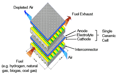 |
Typical solid elctrolyte type fuel cell Courtesy Ceramic Fuel Cells Ltd |
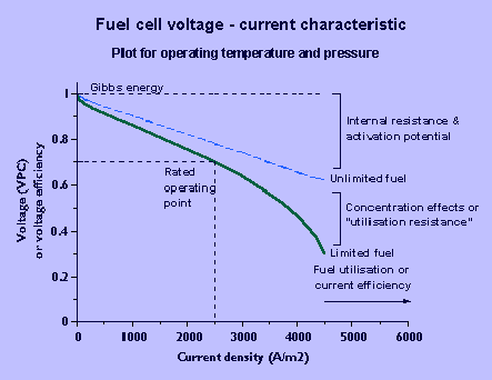 |
| Fuel cell characteristic |
As current increases, the voltage reduces due to the internal resistance, over-potentials, and concentration effects. Provided that excess fuel is supplied, the voltage decreases approximately linearly with current. When the fuel flow rate is limited the fuel utilisation or current efficiency increases with current but the linear relationship still applies up to approximately 80% utilisation.
If the fuel flow is regulated proportional to the current, current efficiency will be constant. Hence the voltage efficiency and overall efficiency is higher at low loads.
The decrease in partial pressure of hydrogen due to increasing current and utilisation of the fuel can be substituted in the Nernst equation. Assuming perfect distribution of fuel or uniform partial pressure over the cell area, the voltage loss is negligible until all the fuel is used due to the high equilibrium constant. When the utilisation approaches 1 a sudden drop in voltage occurrs as ln p approaches -infinity.
However, in practice, at high fuel flows, the partial pressure and concentration of fuel will not reduce to zero simultaneously at all locations in the cell and the transition is smoother. This is shown by the actual voltage-current characteristic which becomes non-linear at fuel utilisations U>80%, and where V>0 when U=1.
The rated full load operating voltage of the fuel cell is chosen as described above, but at lower loads the output voltage of the fuel cell exceeds this. A constant voltage AC supply will normally be required, and for simplicity of the power conditioner, the excess voltage at partial loads may be dumped through a resistance.
Dropping the voltage at low loads by starving the fuel cell of fuel, and hence increasing the fuel utilisation efficiency at low loads has been considered but may be subject to problems:
- The utilisation resistance is normally significantly lower than the internal/over-potential resistance up to the rated current. Hence the utilisation may need to approach unity to achieve the required voltage drop at low loads;
- At near zero currents and fuel flows, mass transfer effects will not smooth out the the transition from low voltage loss to high voltage loss, and stability problems might result.
Due to the relatively flat voltage-current characteristic, and to avoid the above stability problems fuel flow control proportional to load current is recommended.
Since fuel flow is controlled proportional to current, the fuel utilisation or current efficiency will remain constant with current. A fuel utilisation with a reasonable voltage efficiency-current characteristic is selected (For maximum overall efficiency the voltage and current efficiency should be nearly equal but a lesser voltage efficiency will give a compromise between power and efficiency).
A maximum design current is selected on the substantially linear part of the voltage-current characteristic. The crossing point determines the operating voltage. Since excess voltage is dropped at partial loads to maintain a constant AC voltage, the effective DC voltage and voltage efficiency are constant with current (up to the maximum design current).
References
- S Zumdahl; Chemistry; Houghton Mifflin 1997
- P Costamagna & K Honegger; Modeling of Solid Oxide Heat Exchanger Integrated Stacks and Simulation at High Fuel Utilization; Journal of the Electrochemical Society, Vol 145, No 11, 1998
- F Standaerdt, K Hemmes, N Woudstra; Analyticl fuel cell modeling; Journal of Power Sources 63, 1996
- T Swaddle; Inorganic Chemistry; Academic Press 1997
- J Lee & T Lalk; Modeling fuel cell stack systems; Journal of Power Sources 73, 1998
- F Gardner; Thermodynamic processes in solid oxide and other fuel cells; Journal of power and energy, Part A, Proceedings, Institution of Mechanical Engineers, Vol 211, 1997

|