Power Conditioning
ConvertersFor Renewable energy to be harnessed efficiently, power conversion systems have to be deployed. In the Wind Power Sector these converters usually have one of two components or both. They are known as rectifiers or inverters.
Inverters
Inverters convert the DC Power from sources such as batteries or Fuel cells to AC Power. The current signal can then be conditioned using power control electronic systems and transformers. In renewable energy systems, static inverters are used. They have no moving parts.
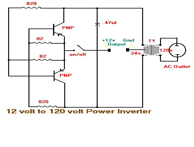
Fig. 1 Power Inverter
From figure 1, DC power is connected to the centre tap of the transformer’s primary winding. The on/off switch is flipped back and forth to allow current to flow back to the DC source following two alternate paths through the bipolar transistors and the voltage divider to the primary windings of the transformer producing AC Power in the secondary windings. Basically, the switch mechanism has two stationary contacts with a spring contact and electromagnet. The current in the electromagnet is interrupted by the current flow allowing the switch to go back and forth quickly. The signal produced is a square wave which in Fourier analysis is the sum of infinite sine wave signals or harmonics. The quality of the output signal depends on the load. In HVDC applications (i.e. three phase), three inverters are connected to each load terminal so that the each switch operates at the 60 degree point of the output creating a six step output square wave which contains the harmonics that represent the AC signal.
Rectifier
The rectifier is the exact opposite device when compared to the inverter. It converts AC power from the induction generator of wind turbines to DC Power for batteries or fuel cells.
The process, called rectification can occur for half-wave or full-wave rectification. This is when the AC signal output has either the positive or negative half cycle blocked. Half wave rectification can also be accomplished by centre tapping a transformer and using two diodes connected back to back. In full wave rectification four diodes are used in the bridge configuration to convert the signal to positive or all negative polarity.
For High Voltage Power Applications, six diodes are used. Each pair works as double diode to enable full wave rectification. See the diagram of a 3 Phase full wave bridge rectifier below (fig. 2).
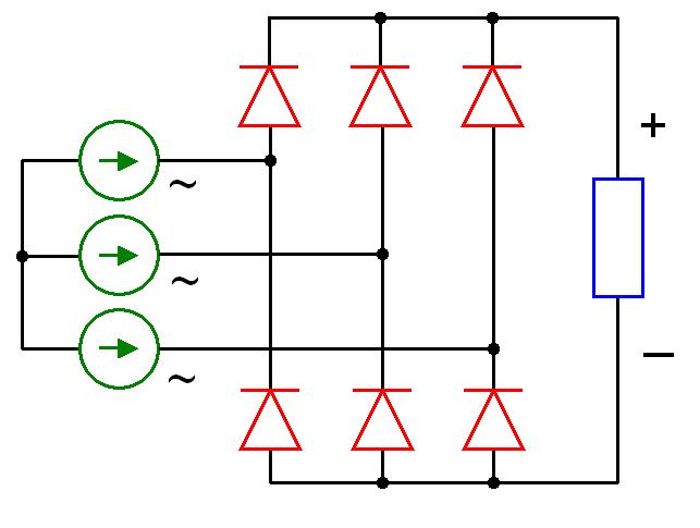
Fig. 2: 3-Phase Full-wave bridge rectifier
Converter Technologies
In selecting from the wide range of converter topologies, the power generator in the wind turbine's nacelle must be matched with the converter that will obtain the maximum power output at different wind speeds. There are 4 kinds of generators available today; they include permanent magnet synchronous generators, doubly fed induction generators, induction generators and synchronous generators. Brief descriptions of converter topologies will be discussed as they are deployed with the wind power generators that maximise output power.
Permanent Magnet Synchronous Generators (PMSG)
These are usually deployed in smaller instead of larger turbines because of the economics of scale associated with magnetic material and the depreciation of these materials. The permanent magnet synchronous generator does not need an external excitation current for the stator. They can also be deployed with diode rectifiers as a result of this. Below are four converter topologies that have been identified to suit deployment with the PMSG.
Thyristor Supply side Inverter
This maximises the converter’s power output by the continuous control of the inverter firing angle (i.e. regulation of the turbine speed through the DC-link’s voltage). It is cheap; it has higher available power when compared to hard-switched inverters. It needs a smoothing system or compensator for harmonic distortion and reactive power demand, see figure 3.
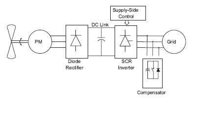
Fig. 3: PMSG and Converter
Hard-Switching Supply side Inverter
To maximise the system’s power output a power mapping technique is used to match the Maximum Power to the DC-link voltage. Furthermore, a derivative control is also used to control the stator frequency as it changes with the DC-linked voltage. The control system is like the MPPT (Maximum Power Point Tracking) which maps the Power generated to a reference power so as to set the operating DC voltage, see figure 4.
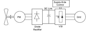
Fig. 4:
Hard Switching Supply side Inverter with Voltage Source Inverter (VSI)
Intermediate Stage DC/DC Converter
The incorporation of an intermediate DC/DC converter is also another design that can be deployed with PMSG’s, see figure 5. Compared to the hard-switching topology the intermediate DC/DC converter is more flexible to strong and weak AC systems. The Control system works by regulating the magnitude of the fundamental line current and the phase angle between line current and line voltage. The VSI is also switched at the frequency of the carrier signal to enable proper output harmonic definition. Also the shaft speed is matched to optimum values of the DC Voltage and current according to the maximum power from the generator. The VSI controller can set the DC-link constant and vary the reactive power so as to maximise real power.
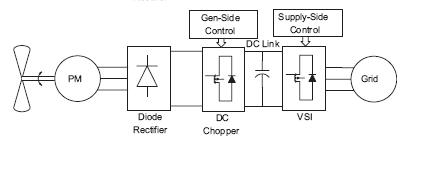
Fig. 5:Intermediate DC/DC converter with VSI
Back to Back Pulse Width Modulation (PWM) Converters
This is implemented with two 6-switch, hard switched converters and a DC-link capacitor. The generator side rectifier is controlled through a Proportional Integral controller such that the direct-axis current is held to zero to obtain maximum torque with maximum current. The MPPT matches the optimum rotor speed as a result of the wind speed to the output power. The supply side controls the line current to the grid using a hysteresis controller, see figure 6.
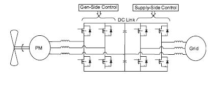
Fig.6:Back to back PWM converter
Doubly fed induction generator (DFIG)
Three distinct systems are deployed with DFIG’s. The Static Kramer drive and Silicon Controlled Rectifier converter methods, back to back PWM converters (the same are used for PMSG’s), matrix converters. One advantage of deploying the DFIG is the ability to output the rated power without overheating. They are excellent for large systems (i.e. MW size). Most of the power generated flows through the stator instead of the rotor, thereby reducing the converter power rating.
Static Kramer drive and Silicon Controlled Rectifier converter
A diode rectifier is connected to the rotor and a line commutated inverter is connected to the supply side. Sliding mode control is used to force the generator torque to be a linear function of the generator speed around the operating point of the maximum power transfer. Thereby, producing maximum power at different shaft speeds, see figure 7.
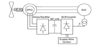
Fig. 7: Static Kramer drive system
Back to back PWM converters
Vector control of the supply side inverter is used, this is done to keep the DC-link voltage constant by regulating the direct axis current (reactive power is also minimised to maximise real power output by altering the quadrature axis current). On the rotor side, direct axis is oriented along the stator flux vector providing maximum energy transfer, see figure 8.
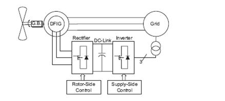
Fig. 8: Back to Back PWM Converter for DFIG
Matrix Converter
It consists of 9-bidirectional switches arranged to allow the any input phase to connect to the output phase at any time, each switch is capable of rectification and inversion. This system is capable of converting the variable AC from the generator to constant AC for the grid see figure 9. The direct axis current is regulated to control the flow of reactive power from the stator, while the quadrature axis current is regulated to control the real power output.
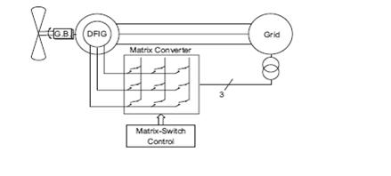
Fig. 9: Matrix Converter for DFIG
Induction generators
They are unique because they require reactive power. If the stator’s rotating magneto motive force is rotating slower than the rotor, then the rotor generates power at synchronous frequency. Usually a capacitor bank is connected in stand-alone systems to the stator to provide the magnetising current for the reactive power. (Note: for grid connected systems the reactive power is drawn from the grid). Induction generators also use back to back converters and fuzzy logic controllers, see figure 10.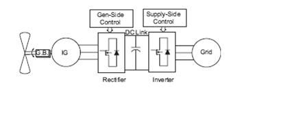
Fig. 10:Induction generator with back to back converters.
Synchronous Generators
Synchronous generators can be deployed with the DC/DC intermediate stage converter as in figure 3. The DC link voltage is controlled by using the amplitude of the 3-Phase inverter voltages and the phase displacement angle of the inverter. For MW-range systems the energy generated by the synchronous generator is converted by back to back PWM VSI’s. The supply side PWM inverter allows for control of real and reactive power transfer to the grid. The important thing to note is that real power must always be maximised.
References:
Jamal A. Baroudi et al; A review of power converter topologies for wind generators
http://hyperphysics.phy-astr.gsu.edu/Hbase/electronic/rectbr.html