Framework >>>

Welcome to the framework section of the website. Please utilise the menu provided below to navigate through the framework structure.
| Energy management | Financial Structure | Assistive Funding | Energy Efficiency | Effective Supply | Social considerations |
Combined Heat and Power (CHP) >
CHP (or Cogeneration) is seen as key to more efficient energy use. This section of the framework gives an overview of the technology and information and links that will provide insight and practical help. CHP has been a key focus of the EEE Case Study . The case study goes through an example of the matching of CHP to the electrical and thermal load for a large estate. The GENcalc Tool has been developed to allow CHP options to be analysed and an optimum implementation selected, it is available for download. The GENcalc Tool contains instructions, commentary and example data from the case study which complement this section.
Contents
Introduction | Background | Technology 1st Principles | Energy Flow Diagram and Energy Equations | Good quality CHP | Environmental, Safety and Social Considerations | Financial Considerations | Maximising Revenue | Legislation~Incentives~Grants | Electricity Regulatory Considerations | Engine Types | Suitable applications | Barriers/ Perceived Risks | Assistance Sources |
Cogeneration or Combined Heat and Power (CHP) is the production of electricity combined with the effective use of the heat produced in the electricity generation process. Cogeneration depends on proximity to a demand for the heat energy.
CHP is the most efficient way of generating electricity, heat and cooling from a given amount of fuel. It saves between 15-40% of energy when compared with the separate production of electricity and heat.
Cogeneration helps reduce CO2 emissions significantly. It also reduces investments into electricity transmission capacity, avoids transmission losses, and ensures security of high quality power supply.
A number of different fuels and proven, reliable technologies can be used. The most common implementation today are gas reciprocating engines or gas turbines. In the future a major role for Fuel Cells technology is anticipated.
CHP schemes can range in scale from Micro CHP (20kWe) to Large scale CHP (600MWe).A concurrent need for heat, electricity and possibly cooling indicates suitable sites for cogeneration.
The initial investment in cogeneration projects can be high compared to conventional technology but payback periods between 3-5 years can be achieved (especially with grant support).
The payback period and profitability of cogeneration schemes depends on the difference between the CHP fuel price and the sales price for electricity. The avoidance of charges associated with Distribution and Transmission of centrally generated electricity and also exemption from levy's on centrally generated power make the CHP generated electricity cheaper despite the difference in economy of scale.
Global environmental concerns, ongoing liberalisation of many energy markets, and projected energy demand growth in developing countries are likely to improve market conditions for cogeneration in the near future.
Most central electricity generation plant in the UK is remote from users of heat energy and the heat energy which is a by-product of the generation process is emitted to the atmosphere as waste (cooling towers, water outflows to sea etc). Additional energy losses are incurred in distributing centrally generated electricity to the points of use.
Cogeneration of electricity and heat at the point of use is the most effective use of primary fuel. Electricity generated through CHP is generally significantly cheaper than imported electricity from the centralised producers, this can give attractive payback periods. CHP does however involve increased up front capital cost compared to conventional power. Systems range from Micro-CHP (3 200kWe), through Small Scale CHP (200 - 1.5MWe) to Large Scale (1.5MWe 300MWe+).
There is variation in the installed base of CHP in different countries.

fig: CHP graph by country, Educogen http://www.cogen.org/Downloadables/Projects/EDUCOGEN_Cogen_Guide.pdf
There is now EU and UK legislation promoting the use of cogeneration.
 In CHP the heat generated in the production of electricity is captured and used to meet thermal demand. In the picture below an engine is used to generate electricity. The heat from the engines is captured from the engine cooling system and the flue gases through heat exchangers and can be used to supply a heat for hot water or space heating etc. It is possible to extract heat at more than one temperature. There can be up to 4 different heat recovery points from engine and generator. The engine can be of many different types (see engine types section).
Energy flow diagram / equations:
The flow of energy in the CHP system is shown schematically below. The energy benefits over conventional grid electricity and boiler generated heat are:
- Avoidance of transmission and distribution network costs and losses
- Heat produced is used rather than dumped to atmosphere
Energy Parameters
- Ef(e chp) = efficiency of electricity production in CHP system (typical 35%)
- Ef(th chp) = efficiency of heat production in CHP system (typical 45%)
- Ef(e grid) = efficiency of electricity production in central generator (typical 40%)
- Ef(th boiler) = efficiency of heat production in standard gas boiler (typical 80%)
Energy Equations
 |
Consider production of 1 kWh electrical + 1.25 kWh thermal:
Gas to generate electrical energy = 1kWh / Ef(e grid) = 2.5kWh Gas to generate thermal energy = 1.25kWh / Ef(th boiler) = 1.56kWh Total primary fuel energy = 4.06kWh Total useable energy output = 2.25kWh Waste Energy = 1.84kWh (45%)
Gas to generate electrical = 1kWh / Ef(e grid) = 2.0kWh Gas to generate thermal = 1.25kWh / Ef(th boiler) = 1.56kWh Total primary fuel energy = 3.56kWh Total useable energy output = 2.25kWh Waste Energy = 1.31kWh (37%)
Gas to generate electrical = 1kWh / Ef(e chp) = 2.86kWh Heat from generation = 2.86kWh * Ef(th chp) = 1.29kWh Total Primary Fuel Energy = 2.86kWh Total useable energy produced = 2.25kWh Excess Heat Energy = 0.04kWth Waste Energy = 0.61kWh (27%) Waste reduced to < 47% of waste energy incurred in conventional processes. |
Good Quality CHP is beneficial to the environment and meets the required regulatory standards (e.g. qualifies for incentives). There are multiple definitions and metrics in the EU. We focus here on the UK scheme
UK CHPQA Quality Index (QI) Metric ( https://www.chpqa.com/ )
CHPQA requirements for good quality CHP (please access website for details) are:
- Power efficiency, Ef(power) >=20% (15% for some special cases till 2005)
- Quality Index(QI) >= 100.
The quality index is defined as follows:
QI = X x Power Efficiency+ Y x Heat Efficiency
Power Efficiency = Power Output (MWhe) / Fuel Input (MWh)
Heat Efficiency b= Utilised Heat Output (MWhth) / Fuel Input (MWh)
X is a factor for power, related to alternative electricity supply options. Y is a factor for heat supply, related to alternative heat supply options. These factors vary to reflect particular classes of CHP plant (table).

Other metrics for good quality CHP are used elsewhere i.e.
- Energy Utilisation Factor (EUF)
EUF = [Elec + Heat Output] / Input Fuel Energy
Good Quality if EUF > (0.75 to 0.85) for various plant types.
- Fuel Energy Savings Ratio (FESR)
FESR = 1 { Energy Input / [Heat Out / Ef(th boiler) + Elec Out / Ef(e grid)] }
= 1 {Energy Input / Energy required in conventional plant for same Output}
Environmental, Safety and Social Considerations
The generation of electricity close to the point of use means that extra focus needs to be put on flue gas emissions. CHP engines need to be maintained properly to meet the required standards, maintenance costs can be high and must be factored into the cost analysis. (note: domestic and estate boilers already installed would be displaced by CHP).
Additional environmental factors that must be considered are noise and electromagnetic emissions from the engine and generator.During installation (especially in the case of new district or wet heating systems) there may be a period of significant disruption. Getting buy-in (marketing) of the customers is key, emphasis of the green and financial objectives driving the work should help here.
Safety concerns associated with the new technology or systems must be considered.
Environmental considerations will be specific to the CHP engine type, the installation and the site.Full environmental, social and safety risk analysis should be carried out together with the vendors, contractors and the customers of the system. The CHPclub can provide assistance.
When assessing options the BEST VALUE is represented by the option with the greatest NPV, section on NPV below, also see ESCO Financing Community Energy section of framework.
Assistance from consultants and also development grants are available through the Community Energy program.
( http://www.est.org.uk/communityenergy/information/fincomenergy.cfm )
Capital and maintenance costs
The CHP Financials' sheet in the GENcalc tool gives a breakdown of the costs associated with installation and running of a CHP system. The tool uses a power curve fitted to data for a variety of sources.
Economics of Electricity (Generation and other charges)
The local generation of electricity avoids Transmission and Distribution charges and may be exempt from some taxes (CCL etc). This differential is a key driver of positive cashflow as generated electricity can be significantly cheaper than that available from the grid.
Note that where excess electricity is generated it can be exported and sold to generate revenues. This can be a key driver of financial performance see Maximising Revenues section.

Displacement of Boiler Costs
The heat generated from the CHP engine will offset the costs associated with running a gas boiler system. Note a gas boiler system may still be required for backup and security of supply.
Net Present Value NPV (BEST VALUE)
The NPV represents the capital cost minus the discounted cashflow at a stated number of years after installation. It is a valuable tool for comparing options and determining BEST VALUE. Government guidelines for the public sector are that a 3.5% discount rate over a 25 year period be used. In the private sector it is more normal to use a 10% 15year NPV.GENcalc provides an NPV for any input option.
Simple Payback
Simple payback is the time taken for the cumulative cashflow to exceed the capital investment costs. It is a parameter used to evaluate the financial merits of a proposed scheme. The GENcalc tool will generate the payback for any input scenario.
Below is a simple example calculation
|
Example of Basic Financial Analysis (without Gov. Aid) (Also see Case Studies): 300kWe / 500kWth engine, capital cost £250k, running 12hr / day = 4380 hr/yr Annual Total kWh(elec) = 1,314,000 Annual Total kWh(thermal) = 2,190,000 Gas input fuel cost 1.25p/kWh Elec grid supply ave cost 6p/kWh Elec CHP gen cost = 1.25p / Ef(e chp) = 1.25/0.35 = 3.6p, saving 2.4p/kWh, Annual Electrical Saving = £31k Saved thermal boiler cost = 1.25 / ?(boiler) = 1.25 / 0.8 = 1.56p/kWh, Annual Gas saving = £34k Total Annual Saving = £65k Simple payback = 4 years. Gross Savings after 10 years = £650k Net Savings after 10 years = £400k Other Customer Benefits (Backup, Space, Maint, Capital, Risk Transfer) Additional benefits to customers that can be factored in are:
Financial sensitivities / Impact of Gas and Electricity Prices The financials are very sensitive to the following parameters. Sensitivity analysis with a range based on latest projections should be carried out.
|
Maximizing Revenues ( http://www.est.org.uk/communityenergy/information/fincomenergy.cfm )
Maximising revenue provides obvious payback benefits and also allows greater portion of the capital to be financed from revenues through lease or loan and can reduce the initial capital investment which can be a barrier to implementation.
Methods of increasing revenue are:
1. Increase load factor (annual hours run) and get more value from same asset .
Options include:
- Increase number and diversity of loads .
- Utilise heat storage to allow (i) optimisation of electricity generation timing to meet peak load tariffs (ii) optimise for case where heat and power demands don't coincide (iii) store surplus heat for supply when heat demand peaks (iv) extend operating hours by extending ability to utilise heat produced.
- Use heat to drive cooling plant additional revenue stream, can utilise summer heat, extends operating hours. (need to carefully analyse the COP for absorption vs electric chillers to confirm benefits, absorbtion COP < electric).
2. Increase value of electricity sales and get more value from same asset .
Background: Since NETA value of electricity exports to grid (licensed supply companies) has declined to 1 1.5p/kWh which is marginally economical .
To be economically viable in current market conditions CHP must sell direct to a customer. Options include:
- Wheeling : utilise generated electricity to offset purchases on other owned sites (offset purchases at 3.54.5p/kWh).
- Use of Distribution System charges need to be paid (ofgem)
- Up to 5MW can be supplied without licensed supplier obligations
- Metering and billing costs incurred
- Sales over public network Target revenue of 3.54.5p/kWh
- Use of Distribution System charges need to be paid (ofgem)
- Customers may benefit from CCL exemption
- Metering and billing costs incurred
- Sales over private wire Target achieving up to 6p/kWh
- Acquire the wires. Buy or rent former DNO wires or install new.
3. Climate Change Levy (CCL) Benefits
- Non Domestic electricity customers supplied by Good Quality CHP or renewables are eligible for exemption from CCL. Domestic customers do not pay CCL..
- Value of this is 0.15p/kWh(th) + 0.43p/kWh(elec)
4. Renewable Obligation (RO, ROCs)
- Applies to Renewable Electricity Only (ofgem)
Legislation / Incentives / Grants
Grants are co-ordinated by Community Energy http://www.est.org.uk/communityenergy/index.cfm
Development Grants :
Community Energy provides up to 50% of the funding you need to carry out development work on a community heating scheme.
Development work tends to fall under three main headings, all of which are eligible for grant support:
1. Option Appraisal - this could take the form of:
|
|
Click here for a template for options appraisal.
2. Business Planning - which should include:
|
|
Click here for a business plan template .
3. Preparation of tender documentation for a community heating scheme
Call the Helpline on 0870 850 6085 to talk to a Community Energy expert about your scheme.
Download a Checklist: Steps to Securing a Development Grant .
Click here for Development Grant Guidance notes.
Click here for a table of development grants awarded.
Capital Grants:
Community Energy can fund up to 40% of the capital costs of implementing your community heating scheme.
These capital costs could include an energy centre, pipework or internals for buildings or dwellings. The Royal South Hants Hospital , for example, was awarded £93,000 towards the cost of installing CHP into an existing energy centre to serve 7 hospital buildings. Woking Borough Council received £545,000 towards the extension of its community heating and private wire electricity services to 900 homes across the Borough.
You and your consultant should work together to identify how a Community Energy grant could be used and then prepare a capital grant application. Electronic application forms are available from the Helpline on 0870 850 6085.
The approval rate for capital grant applications is around 80%. And don't be disheartened if your capital application is not approved: if you work closely with the programme team to strengthen and resubmit your application, you'll have a 90% likelihood of being approved second time round.
![]() Download a Checklist: Securing a Capital Grant
Download a Checklist: Securing a Capital Grant
![]() Find out more about Funding a Community Energy Scheme
Find out more about Funding a Community Energy Scheme
![]() Read more about Successful Community Energy Schemes
Read more about Successful Community Energy Schemes
Free Expert Support
As you develop your community heating scheme, you will be given free expert support by the Community Energy team, support which has, to date, greatly increased the chances of success of grant applications. Our expert advisers are there to help you - they will:
• talk you through the programme prospectus and answer your questions about Community Energy
• help you understand how your scheme fits within the timescales of the programme
• advise you on what makes a good Community Energy application
• talk you through the relevant grant application forms
• help you understand the context and policy drivers of community heating - eg, carbon reduction targets, PFI, housing transfers
• ensure that you understand the stages of delivering a scheme
• help you to develop support within your organisation
• advise you on how to select and work with external consultants
• encourage you to consider linking your scheme to adjacent sites
• advise you on the best operational structure for your scheme - eg, managed in-house, setting up an ESCo
• advise you on relevant electricity market issues
• monitor your progress after you've been awarded a grant to ensure that your scheme is on track
Call the Helpline on 0870 850 6085 to be allocated an expert adviser.
Enhanced Capital Allowances
The Government allows investments in energy efficient plant and machinery to be set against income tax or corporation tax in the year in which the expenditure is incurred, rather than (as with other investments) over a number of years.This includes investment in CHP. Energy Services Companies (ESCO's) can claim allowances on their investment in community heating under a comprehensive energy management contract. However, organisations that are non-profit making (e.g. universities and hospitals) have no tax liability to set allowances against. Leased assets are also eligible for enhanced capital allowances (ECA's), where a bank usually owns the equipment and is able to claim ECA's. However, the bank does not automatically pass the benefit to thelessee, so this needs to be specifically investigated. CHP must be certified as Good Quality under the CHP Quality Assurance programme www.chpqa.com . Biomass boilers can also qualify for enhanced capital allowances. In addition to plant and machinery, some long-life assets (with an economic life of 25 years or more (from new) qualify for ECA's.This enables businesses including developers to claim a proportion of the cost of the equipment of the community heating scheme against taxable profit. Heat distribution pipework is not currently considered to be ancillary to CHP, so does not qualify for ECA's. Only the pipe insulation can qualify and on the condition that it meets the designated standard criteria (BS 5422).
However, the pipe insulation eligibility depends on:
- The boundary of the CHP scheme.
- Whether the pipes are fixtures.
- Whether the claimant has a qualifying
- Interest in the land.
For further information see www.eca.gov.uk
Electricity Regulatory Considerations
The Exempt Supplier regulations [Electricity Supply Regulations 2001] mean that a supplier of less than 2.5MWe (5MWe in some cases) is exempt from Transmission charges and need pay only locally negociated fair charges (ofgem) for use of the distribution network (typically 1 1.5p / kWh).
The following technologies are currently in widespread use:
- Steam turbines
- Gas turbines
- Combined Cycle (gas and steam turbines)
- Diesel and Otto Engines.
These technologies are readily available, mature, and reliable.
Three other technologies are on the market:
- Micro-turbines
- Fuel cells
- Stirling engines.
In summary:

http://www.uneptie.org/energy/act/re/fs/docs/cogeneration.pdf
CHP Scheme Design and Operation Options
For cogeneration plant there are three main operating regimes. The GENcalc tool provides information and allows each option type to be evaluated for a given demand profile. The Chooser sheet within GENcalc can be used to select the best option.
Note that the CO2 impact can still be positive to the environment even when excess heat is being generated and dumped to the atmosphere (broadly the energy impact is positive until the heat dumping is equivalent to the average heat dump of the grid).
Base Load Operation
The unit is operated to provide base load electricity or thermal output. Any shortfall is supplemented with electricity from the public supply, and heat from stand-by boilers or boost heaters. In our case study this option gave best lowest capital.
Load Following Operation
The unit is operated to follow electricity or thermal demands. Any excesses or are exported or dumped, shortfalls supplied from the grid or boilers. In our case study this option (electrical load following) gave best CO2 saving per £ Capital spend.
Electricity Generator Operation
The unit is operated to provide excess electricity. The excess electricity is then exported and sold to customers to generate profits. The excess heat is sold to customers (consider absorbtion cooling) to generate revenues. This configuration allows island mode operation in cases of grid failure. This mode of operation is being followed in Woking . In our case study this option gave best NPV and CO2 saving but was highest capital.
|
The optimum regime for each site depends on: Electricity purchase and export tariffs Cost of fuel Availability of off-site heat and electricity customers Efficiency of stand-by heating plant Maintenance costs Other cogeneration operational costs (e.g. maintenance, auxiliary power requirement). |
Connection to the public supply:
Cogeneration systems are most often designed to operate in parallel mode. There are mandatory requirements for the provision of protective controls and procedures. It is vitally important that the installed power plant is able to remain stable, i.e. to maintain synchronism when disturbed by load changes and system faults. A detailed evaluation of site electrical loads is an essential part of the initial design study. This will include analysis of switchgear and transformers, operational sequences, load flows and fault levels (i.e. the maximum current that can flow under a 3-phase short circuit condition). The existing public network and site network may need to be modified or reinforced to permit the installation of the cogeneration scheme. It may be advantageous for some systems to be able to operate in island mode, that is, entirely independently of the public supply system. In particular, island mode enables the system to continue operating during times of public supply failure (a parallel-only installation shuts down with the grid). The proportion of the site capable of operating under island mode depends on installed capacity and its characteristics. The practicalities of this mode of operation need to be carefully considered, as it may require load-shedding facilities that will add to the cost of the installation. Standby Power and CogenerationCogeneration plant can be integrated with standby electrical plant. In some cases integration may not be a cost effective option, especially for small-scale applications. However, the use of cogeneration plant as full or partial standby can be a significant advantage and, for some sites, has been one of the deciding factors in choosing cogeneration. In cases where cogeneration alone is to provide the standby requirement, sufficient plant capacity and number of units must be provided to ensure security of supply and to cover maintenance downtime.
Identifying Suitable Applications
CIBSE CHP Group advice
CHP should always be considered when:
- designing a new building,
- installing new boiler plant,
- replacing/refurbishing existing plant,
- reviewing electricity supply,
- reviewing standby electrical generation capacity or plant,
- considering energy efficiency in general.
Further information about when and how to consider CHP is provided in Good Practice Guide - Combined Heat and Power for Buildings and CIBSE Applications Manual 12.
Although the profitability of cogeneration generally results from its cheap electricity, its success depends on using recovered heat productively, so the prime criterion is a suitable heat requirement. As a rough guide, cogeneration is likely to be suitable where there is a fairly constant demand for heat for at least 4,500 hours in the year.
The timing of the site's electricity demand will also be important as the cogeneration installation will be most cost effective when it operates during periods of high electricity tariffs, that is, during the day.
Certain building sectors are more appropriate than others for cogeneration due to their typical demand profiles note that this is just a rough guide and specifics should be reviewed for all cases. At a first approximation the probability of a good fit is assessed below:
Hotels +++
Hospitals +++
Swimming Pools / Leisure Centres +++
High density housing ++
Residential +
Commercial +
Supermarkets ++
Industrial ++
University / Govt Estates +++
Restaurants -
Shopping Malls ++
Key Initial Questions (Not appropriate for Micro-CHP):
- Have all other energy saving measures been identified and either implemented or taken into consideration?
- Is there a simultaneous base load requirement for electricity and heat which exceeds 20 kWe and 50 kWth respectively for more than 4,500 hours/year?
- Are there any site changes/developments planned?
Technology : CHP is a mature technology. With proper engineering, risks such as downtimes, failures, and reduced efficiency are not greater than for most combustion technologies.
Environmental : Environmental problems such as air emissions, noise, raw material and residue handling, can all be mitigated through proper siting, design, and operation of the CHP facility. In many cases CHP retrofits to existing installations may bring environmental improvements.
Planning :
The ratio between electricity and fuel prices may change (price risk);
Regulatory frameworks may change unfavorably (regulatory risk);
The heat demand may change, making the CHP project less suited to meet the site's needs (energy consumption risk);
The organization that uses the CHP scheme may close, relocate, or go bankrupt (host risk).
Main Advice / Assistance Sources
UNEP, EDUCOGEN, COGEN, CHP CLUB, CHPQA, ACTION ENERGY, COMMUNITY ENERGY, CIBSE.
| Energy management | Financial Structure | Assistive Funding | Energy Efficiency | Effective Supply | Social considerations |
Absorption Chillers Technology summary >
Environmental Benefits | Application in Buildings | Operational Description | Worked Example |
Environmental Benefits
Absorption chillers offer an exciting alternative to conventional compressor chillers, since their main energy input is heat instead of mechanical power (mostly electricity). Since the heat required is at a relatively low temperature, the application fits to most waste heat rejection found in industrial processes, chp, etc.
Application in Buildings
The generalization of adsorption chillers, working at lower heat temperatures, is starting to make viable thermo solar cooling.
Absorption chillers are more expensive and bulkier than conventional compression chillers. Yet, they are commonly used in buildings whenever gas tariffs (for fire based absorption chillers) or excessive waste heat turns them economically viable. The typical applications are:
• Gas fired absorption chillers (benefits form gas tariffs)
• Steam absorption chillers (waste heat in the form of steam)
• High temperature hot water absorption chillers (high temperature waste heat)
• Low temperature hot water adsorption chillers (low temperature waste heat)
There is a heat rejection in all absorption and adsorption chillers at a very low temperature (between 30 ° C and 50 ° C), that must be dissipated by dry coolers.
Operational Description
Absorption chillers work much like conventional compression chillers, except that there is no compressor, and instead, the vapour is absorbed by a solution (in the absorber), pumped, and regenerated with heat (in the generator). Typically, if ammonia is used as refrigerant, water will be the absorber, although lately the combination water (refrigerant) lithium bromide (absorbent) is becoming more popular. The COP will depend on the temperature of the regenerative heat with a minimum around 90 ° C. The pump work is usually considered negligible.
In the last years, an interest moved by solar cooling technologies recovered adsorption chillers. Adsorption chillers working principle is similar to absorption chillers, yet they store the vapour in silica gel, that can be regenerated with much lowers temperatures, ranging from 5°C to 95°C. Unfortunately, the COP drops considerable, as can be assessed in the following image, representing the variation of the refrigeration capacity with the regenerative heat temperature.

Chilled water temperature can be lower than in conventional chillers, being possible in ammonia water/glycol chillers, an output temperature as low as -10 ° C (good for ice storage).
The capital cost is 1.5 2.5 superior than compression chillers (the capital cost varies from 200£/kW to 500£/kW, including necessary dry coolers), and the COP is usually inferior than 1 (depends on the regenerative heat temperature).
Worked Example
Please check Cooling Calc page of the DemCalc Tool from the downloads section.
Heat Pumps technology summary (Air source, water source and ground source) >
Environmental Benefits | Application in Buildings | Operational Description | Worked Example
Environmental Benefits
Heat pumps potentially offer an energy-efficient method of providing heating and cooling in buildings. They have the ability to make use of waste heat, low grade renewable and ambient surroundings heat sources. Low grade heat held in the air, water and ground, continuously replenished by the sun, can be exploited. By applying a little more energy, a heat pump can raise the temperature of low grade heat energy to a useful level. Similarly, heat pumps can also use waste heat sources, such as from industrial processes, cooling equipment or ventilation air extracted from buildings.
Application in Buildings
Heat pump applications in buildings can be divided into the following operational categories:
• Space heating and/or domestic water heating
• Space heating and cooling only
• Water heating only
Operational Description
Heat pumps typically operate on the principle of the vapour compression cycle. The compressor can be driven by an electric motor, gas engine or absorption cycle (waste heat). The difference between the temperature of the heat source (air, water, and ground) and the desired temperature is known as the temperature lift. The most energy efficient performance is achieved when the temperature lift is small. Typically a higher efficiency is achieved from ground or water source heat pumps than when outside air is used as the heat source. The highest efficiency is achieved when waste heat sources are used.
The heat pump transfers heat from a low temperature source to a higher useful temperature by circulating a fluid through four main components; a compressor; condenser, expansion valve and evaporator. They utilise the fact that the boiling temperature of a fluid rises as the pressure increases.
The steps below describe the process of a vapour compression cycle heat pump using a refrigerant as the working fluid:
 Step 1 : The refrigerant evaporates in the evaporator and as such takes in heat from a low temperature heat source (air, water or ground).
Step 2 : The refrigerant vapour is compresses to a high pressure and temperature.
If the absorption cycle is being utilised the compression is achieved thermally rather than mechanically. The refrigerant is gives off heat when absorbed in a solution, the solution is then pumped to a higher pressure and then heat is applied in the generator to release the refrigerant vapour at high pressure and temperature. The most common working pairs for absorption systems are; water (working fluid) and lithium bromide (absorbent) or ammonia (working fluid) and water (absorbent).
Step 3 : The compressed vapour condenses and gives off useful heat. Due to the higher pressure the temperature of condensation is higher than the temperature of evaporation.
Step 4 : The refrigerant is reduced to a low pressure and the cycle begins again.
Theoretically, heat pumping can be achieved by many more thermodynamic cycles and processes, for example the Stirling and Vuilleumier cycles.
Heat Sources:
The technical and economic performance of a heat pump is closely related to the characteristics of the heat source. An ideal source for a building application would be at a high temperature, stable and available during the heating season.
The following heat sources can be exploited for use in domestic and commercial building applications; ambient air, soil, ground water, loch, river water, geothermal rock, exhaust air and waste water.
Closed loop ground source heat pumps are most commonly used in commercial applications. They consist of a heat pump linked to a closed loop heat exchanger buried in the ground. The heat exchanger is a network of thermoplastic piping through which water is circulated and energy is transferred indirectly via a heat exchanger to the heat pump refrigerant.
The example below compares the capital and running costs, of a conventional and a ground source heat pump system, for a typical office block with a peak heating load of 500kW and a peak cooling load of 400kW. (Electricity cost 0.045p/kWh, Gas cost 0.017p/kWh).
|
Capital Costs Conventional : 2 x 250kW Condensing Gas Fired Boilers £ 15,000.00 2 x 200kW Air Cooled Free Cooling Chillers £ 52,000.00 LTHW & CHW Pumps £ 16,000.00 Testing & Commissioning £ 4,500.00 Total £ 87,500.00
Geothermal : 5 x 80kW Water to Water GSHP £ 79,300.00 60 Boreholes and Pipework £ 16,000.00 Ground Loop Pumps £ 7,000.00 Ground Loop Installation £107,000.00 Testing & Commissioning £ 3,750.00 Total £ 213,050.00 Net increase in capital cost £125,550.00
Running Costs Conventional : Electrical Power - Air Cooled Chillers 407,944 kWh £17,134.00 Chilled Water Pumps 23,167 kWh £ 973.00 Heating Circulation Pumps 22,278 kWh £ 936.00 Natural Gas - LTHW Boilers 1,043,910 kWh £17,746.00 Total £36,789.00
Geothermal : Electrical Power - 5 x 80kW Heat Pumps 346,560 kWh £14,556.00 Ground Loop Pumps 28,274 kWh £ 481.00 Natural Gas - Nil £ 0.00 Total £15,037.00 Net decrease in running cost £21,752.00 Simple Payback (Marginal Cost) 5.8 Years Simple Payback (Full replacement cost) 9.8 Years |
Sources: http://www.heatpumpcentre.org/tutorial/home.htm / Energy Efficiency in Buildings, CIBSE Guide F, 1998 / General Information Report 72: Heat Pumps in the UK a monitoring report, BPP, 2000
Thermal Storage Technology summary (Hot water, chilled water, ice) >
Environmental Benefits | Application in Buildings | Operational Description
Environmental Benefits
Thermal storage offers the benefit of offsetting demand and supply storing energy. This allows not only the use of renewables as primary sources but also the economical flexibility for selling/buying energy at the right period.
Application in Buildings
Thermal storage is commonly applied in buildings to a certain extension. Hot water tanks and chilled water tanks are normally found. The thermal storage can be:
• Water Storage
• Ice Storage
• Low Temperature Fluid/Phase Change Materials Storage
We suggest a look a the site [ http://cipco.apogee.net/ces/hussts.asp ] for another view of thermal storage.
Operational Description
The following table shows some of the drawbacks/advantages of different TS available:
| WS | ICE | LTF | |||
| Volume | - | + | 0 | ||
| Footprint | 0 | + | + | ||
| Modularity | - | ++ | + | ||
| Economy-of-Scale | ++ | - | + | ||
| Energy Efficiency | ++ | 0 | + | ||
| Low Temp Capability | - | + | ++ | ||
| Ease of Retrofit | ++ | - | 0 | ||
| Rapid Discharge Capability | + | - | + | ||
| Simplicity and Reliability | ++ | 0 | + | ||
| Site Remotely from Chillers | ++ | - | ++ | ||
| Dual-use as Fire Protection | ++ | - | - |
Water Storage
Water storage is used to accumulate thermal energy in form of hot or chilled water. It consists on (usually) an insulated water tank, where heat/cold is stored sensibly.
Low Temperature Fluids ( LTF ) are also used for storing cold sensibly instead of water, but at a lower temperature than the conventional systems, hence augmenting the stored temperature difference (and energy capacity). The efficiency will depend only on the thermal losses of the tank, and the storage time. Usually efficiencies around 95% are considered.
Ice Storage
Ice Storage allows storing cold latently. Usually water with glycol or any brine is cooled to very low temperature. That liquid circulates through a series of heat exchangers, freezing the liquid inside the ice tanks (charging mode).Typical applications are charging the banks during the night (low condenser temperatures as well as low electricity costs), using later for the cooling peaks (discharge mode).Ice storage can generally be classified as "Full Ice-storage" and "Partial Ice-storage" systems, depending on the amount of air-conditioning load transferred from the on-peak to the off-peak period. In a "Full Ice-storage" system, the refrigeration compressor does not operate during on-peak periods, and all the cooling is supplied from the ice stored.

In a "Partial Ice-storage" system, some or all of the refrigeration compressors operate during the peak period to supplement the cooling supplied by the stored ice.
The "Partial Ice-storage" system reduces the size and cost of the ice storage tanks and the refrigeration compressors. However, the saving in electricity costs is not as significant as using the full storage because of the need to operate compressors during the peak period. The optimum amount of storage is achieved by maintaining a minimal equipment cost while maximising electricity savings.

Average Operational Efficiency (%): about 90% (1kwh/10kg ice)
Ice storage is a developing technology, and new methods of generating ice are still being developed. For a more extended view on the subject we recommend a look at the following site: http://cipco.apogee.net/ces/xct.asp
PCM
For hot water storage Phase Change Materials (PCMs) are beginning to be generally applied, adding a latent storage component when the temperature rises beyond 40ºC. An example of a PCM storage capacity diagram is showed on the following picture, and includes a comparison with water and concrete storage.

Solar Hot Water Heating Technology Summary >
Application | System Operation | Performance & Costs | Guidance available & references
Application
Solar panels usually mounted on the roof deliver warm water heated by solar energy to pre-heat stored water in domestic hot water cylinder. Hence off-setting traditional fossil fuel heat generation.
There are many types of solar collector. The two types most common in European buildings are the flat plate and the evacuated tube types.
In the flat plate type the medium flows through the absorber.

In the evacuated tube type the absorber strip is located in an evacuated glass tube. The heat transfer fluid flows through the absorber directly in a U-tube or in countercurrent in a tube-in-tube system. The fluid vaporizes even at low temperatures. The vapour rises in the individual pipe and warms up the carrier fluid through a condensing heat exchanger.

Suitability:
- Technical constraints
Savings will depend on size and type of solar collector, and orientation of panels. Ideally solar panels should face south +/- 45o. A dual coil cylinder and additional controls are usually required (although at least one system is made which claims to heat water in the hot water cylinder directly).
- Non-technical constraints
A suitable site is required for the solar panel, which means that the technology may not be suitable for all dwelling types, and there may be planning issues in some areas.
- Trigger points for work
Repairs to roof and/or major works to hot water system.
System operation
Typical system layout:
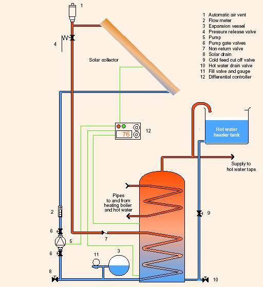
Source - General Information Report 88 'Solar hot water systems in new housing - a monitoring report, Action Energy
Maintenance
Solar collector may need periodic cleaning, and electromechanical components (e.g. circulation pump) will need to be replaced periodically.
Performance & Costs
Key parameters are the annual heat output of the solar water heating system in kWh/m² and the capital cost in £/m² of the system.
For flat plate collectors the annual heat output values typically achieved in the UK are around 370 kWh/m² [Solartwin, EST]. In Denmark values have been achieved of 404 kWh/m² and Sweden 350 kWh/m² [caddet]. In Paris 495 kWh/m² and Perpignon 658kWh/m² [Renewable Energy]. The values depend on system specification and insolation conditions for a given location.
The evacuated tube type of collector can give around 33% more energy capture per m² [EST].
Flat plate system costs range from around £960/m2 (commercially installed domestic - Solartwin) [Solartwin, EST] to £140/m² for large scale (10,000m² district heating Kungal, Sweden) [caddet]. These costs are before government grants and subsidies are applied.
Evacuated-tube collectors are substantially more expensive (eg 300 £/m² for large scale).
The selection of the appropriate solar collector depends scale of the heat demand, the required temperature of the solar heat and the available collector area. In general where the requirement is for normal domestic hot water and there is not a constraint on available area then the flat plate type of collector is most cost effective however as technology is dynamic a case by case analysis should be carried out.

To be effective in utilising the heat captured, systems incorporate a thermal storage mechanism, usually a water tank, also the system may incorporate electrical pumping, these factors must be considered when the systems are being analysed.
|
Saving & cost figures from a 100-house installation of flat-plate SHW in Wales - General Information Report 88 'Solar hot water systems in new housing - a monitoring report, Action Energy). Annual Useful Solar Output (USO) = 294kWh/m² Parasitic Pump Energy = 86.2 kWh (8%) Annual Solar Fraction (% of total energy from solar) = 55% £1400 per SHWS (4m² collector) - purchased in bulk. Typical costs are between £2500-4000 per household system Operating & maintenance cost estimates =£20 per annum Simple Payback = 86 years (Gas @1.4p/kWh)Zero emissions from solar!Source - This data is based upon a monitored EU program in South Wales with 4m² solar collectors per house. HW demands of around 1000kWh. Other sources estimate 3000Kwh as typical. |
Examples of large scale solar water heating were identified in the caddet database [caddet ].The Aeroskobing district heating plant on the island of Aero uses 5000m² of flat panel solar collectors combined with 1400m3 of storage to supply 2.1GWh pa. The plant cost £854k. The system was supplied and is managed by ARCON Solvarme A/S. The solar heating is in combination with straw and woodchip boilers to fuel the district heating network to 550 consumers. The cost per m² of the solar system is £170. The thermal output is 420kWh/m² per year.
The Kungalv district heating plant in Sweden utilises 10,000m² to supply 3500MWh per year. The plant cost £1.4M. The cost per m² is £140 and the thermal outut per m² is 350kWh/yr.
Examples of medium sized solar water heating installations in hotels in europe were documented in the Renewable Energy article When the sun shines on the academy [Renewable Energy]. The Solar academy' in Paris has 73.5m² of flat panel collector in a system that delivers 495kWh/m² per year . A second hotel in Perpignon delivers 658kWh/m² per year .
The financials for the solar hot water system are very dependent on the fuel that is displaced and its cost. Electric water heating replacement gives the biggest gain. If there is excess heat available from electricity generation in the summer time then the solar water heater has no overall impact and should not be considered unless the heat can be used or exported.
Technical Guidance Available & Refererences
Energy savings trust http://www.est.org.uk/bestpractice/hardtotreat/solarwaterheating.cfm
Solar Trade Association www.solartradeassociation.org.uk 01908 442290
CADDET Renewable Energy www.caddet-re.org 01235 436806
GIR 88 'Solar hot water systems in new housing - a monitoring report
Solarserver http://www.solarserver.de/wissen/sonnenkollektoren-e.html
Solartwin http://www.solartwin.com/payback_calculator.htm
CADDET, District Heating Plant 100% Fuelled by Solar Energy and Biomass, http://www.caddet-ee.org/public/uploads/pdfs/Brochure/no161.pdf
The Solar District Heating Plant in Kungälv, Sweden, http://www.caddet-ee.org/infostore/display.php?section=1&id=4670
Renewable Energy: Catching the sun - SHW for hotels http://www.jxj.com/magsandj/rew/2002_05/catching_the_sun.html
additional background at : http://www.itdg.org/html/technical_enquiries/docs/solar_water_heating.pdf
Photovoltaic Technology Summary >
Description | Application in Buildings | Performance Table |
Description
PV cells are made of sandwiched layers of semiconducting material (usually silicon) similar to those used in computer chips. When sunlight is absorbed by these materials, the solar energy knocks electrons loose from their atoms, allowing the electrons to flow through the cell to produce electricity.
Crystalline PV cells: These are either grown from a single crystal (mono-crystalline) or formed by pouring molten silicon into a mold (polycrystalline). Solar modules made from either of these cells will have a conversion efficiency of approximately 14%. Mono-crystalline cells tend to be flat black or deep blue in color. Polycrystalline cells have a mottled (like galvanized steel), cobalt blue appearance.
Thin film PV: This is a thin film of semiconductor deposited on glass and encapsulated by another sheet of glass or opaque backing material. When silicon is the semiconductor, this process is sometimes referred to as amorphous silicon. Thin film solar modules are half as efficient (5%-7%) as crystalline modules, but they are also half the price. These modules have a charcoal grey or bronze color and look like low-E coating or fretting when used on vision glass. Other colors are available but the cost will be higher.
Application in Buildings
Building-integrated PV (BIPV)
PV systems can easily be located on building rooftops, or installed as part of the building's shell. True building integrated PV (BIPV) systems are incorporated into a building at its design stage. Such BIPV systems have the lowest first cost because they replace other sometimes costly building materials (roofing materials, atriums, facades) they require no additional support structures, and additional construction expenses are limited. They may also be used to induce natural ventilation, pre-heat air or be combined with SHWS.
Ancillary equipment
DC to AC inverters, batteries (optional), any additional electrical control devices (meters, line conditioners, etc), wiring and connectors (including junction boxes), and mounting hardware (excluding slope glazing or curtain wall systems).
Performance Table - energy savings and costs
| Hybrid (mix of monocrystalline & amorphous) | Monocrystalline | Standard polycrystalline | Silicon film & ribbon polycrystalline | Thin film amorphous | ||||
| Typical applications | Modules, especially where space is limited. | Modules, rain screen cladding. Also laminated in glass. | Modules, tiles,slates. Also laminated in glass. |
Facades, decorative cladding. | Modules, rain screen, tiles, slates, large roof areas or facades. | |||
| Conversion efficiency at standard test conditions* | 17% to 18.5% | 14% to 16% | 11% to 13% | 9% to 10% | 7% to 8% | |||
| Area needed (m²) per kWp in UK | 6·5 to 7 | 8 to 10 | 11 | 12 | 15 to 18 | |||
| Performance in low or diffuse light conditions | Excellent | Good | Good | Very good | Excellent | |||
| ***Installed cost £/kWp | 5000 to 8000 | 5000 to 13000 | 5000 to 13000 | 5000 to 8000 | 4000 to 8000 | |||
| ***Installed cost £/m² | 850 to 1250 | 850 to 1300 | 500 to 1200 | 500 to 700 | 300 to 450 | |||
| **Approximate annual BIPV energy generated (kWh/m²) | 120 to 130 | 75 to 90 | 65 to 70 | 65 | 50 to 60 | |||
|
||||||||
Additional note: Most crystalline modules have an optimal operating temperature of 40°c. However if the back of the unit will not be exposed to the air, the temperature can rise to 60°c or more during normal operation. This excessive temperature can reduce the modules efficiency by as much as 10%. Orientation and interference are also issues. Mounting a module in the vertical position can reduce potential output by more than 40%. Also, a shadow across one portion of a module can reduce output for the entire module and any other module that is electrically connect to it in series. The shadow from a poorly placed railing is enough to have a significant impact on power production.
Wind Generation Technology Summary >
There are a variety of options for wind energy in an estate, the appropriate solution will depend on the constraints of the particular estate being analysed. Constraints will depend primarily on the physical layout and location of the estate, the construction of the buildings and the acceptable noise levels. The noise level that can be tolerated will depend on the normal background e.g. where traffic noise is present then wind turbine acceptable noise level may be higher.
A recent study by Tameside Council showed that larger turbines were most cost effective but that smaller turbines could be viable. This study is available through the governments practical help to local authorities website. This study also stated that vertical axis wind turbines (VAWTs) may have advantages over more standard horizontal axis wind turbines (HAWTs) although all systems that are proved in volume today are of the HAWT type (http://www.practicalhelp.org.uk/downloads/Tameside_%20Met.pdf).
The wind generation options can be categorised as follows:
| Large scale stand alone wind turbines (>100kW) | Small scale roof mounted wind turbines (<10kW) | Building integrated wind turbines | Small to medium scale stand alone wind turbines |
1. Large scale stand-alone wind turbines (>100kW)
There are increasing numbers of examples of large scale stand alone wind turbines being implemented in the urban environment. Where there is a background traffic noise then the noise impact of these larger wind turbines is not a barrier.
A good example is the 600kW turbine installed in the Sainsburys distribution centre in East Kilbride outside Glasgow . This turbine is within the grounds of the centre and within an industrial estate.
A second example is the Toronto where a 750kW turbine has been installed within an exhibition centre estate as a green icon for the city. The Toronto turbine has been used to study the impact of the turbine on bird life the impact was found to be insignificant in this case.
Links:
Sainsburys East Kilbride: http://www.scotland.gov.uk/pages/news/2001/09/SE4063.aspx
Toronto: http://www.canwea.ca/downloads/en/PDFS/Toronto_Case_Study.pdf
2. Small scale roof mounted wind turbines (<15kW)
There are many examples of roof mounted turbines. In certain situations the buildings can provide an enhanced airflow and higher than typical windspeeds achieved.
Proven Engineering has 600W and 2.5kW roof mounted turbines (HAWTs) installed and is projecting that 15kW turbines and larger can be installed where building design is appropriate.
Windsave (Glasgow) and Swift (Edinburgh) are examples of simple roof mounted wind turbines (HAWTs) which will offset some of the electricity demand in a domestic establishment although these are restricted to the 500W 1.5kW range.
The roof mounted VAWTs are mostly in the stage of being commercially proven in volume at the moment with machines available in the 500W to 4.5kW range. Advantages stated for these machines are lower noise and smaller footprint. There is a trial underway in the Netherlands with multiple manufacturers and there are offerings from Canada (Westech) and USA (Wyndpower).
A novel ducted wind turbine has been developed by Strathclyde University .
Links:
Tameside: http://www.practicalhelp.org.uk/downloads/Tameside_%20Met.pdf
Windsave: http://www.windsave.com/wind_main_content.html
Swift Wt: http://www.renewabledevices.com/swift.htm
Proven: http://www.eru.rl.ac.uk/BUWT/BWEA25%20Proven%20KM.pdf
Westech ( Canada ) HAWT and VAWTs: http://www.westtechenergy.ca/devel.html
Wyndpower (USA) VAWTs: http://www.wyndpower.com/aboutus.html
NL VAWTs: http://www.cnr.umn.edu/FR/degprog/webclass/NRES1201/Dutch%20to%20test%20urban.pdf
Strathclyde ducted: http://www.esru.strath.ac.uk/EandE/Web_sites/01-02/RE_info/Urban%20wind.htm
 3. Building integrated wind turbines
There are proposals for building integrated wind turbines where the building acts as a collector for the wind and funnels the air through the turbine. This has only been a study project so far and has not yet gone beyond the modelling and analysis stage.
Architecture paper: Wind energy for the built environment' - http://www.bdsp.com/web/
 4. Small to medium scale stand alone wind turbines
There are many examples where tower mounted wind turbines have been integrated easily into the urban environment at sites such as schools and commercial establishments.
Links:
Cassop School County Durham 50kW: http://www.catchgate.durham.sch.uk/PAGE17.HTM
e.g. Cumbernauld Primary School 6kW http://www.scotland.gov.uk/library5/education/csbo-08.asp
BP petrol stations London : http://www.eru.rl.ac.uk/BUWT/BWEA25%20Proven%20KM.pdf
| Energy management | Financial Structure | Assistive Funding | Energy Efficiency | Effective Supply | Social considerations |