


|
|||||||||||||||||||||
|
|
|
|||||||||||||||||||
Ocean thermal energy conversion utilises this 22oK temperature difference between equatorial surface waters and cold deep ocean water in order to generate electricity. One of the main processes can be compared to the steam cycle that operates within conventional power plants, replacing ammonia as the working fluid. Ammonia is a common solvent used extensively in the chemicals and manufacturing industries and has, in most refrigeration systems, replaced ozone depleting CFC's.
The idea of OTEC dates back to 1881 when a French Engineer by the name of Jacques D'Arsonval first envisioned OTEC. Like many visionaries he never achieved his dream of producing electricity through Ocean Thermal Energy Conversion. However, Georges Claude, a student of D'Arsonval, believed in the idea enough to embark on a program to demonstrate that Ocean Thermal Energy Conversion for power generation could be practical. Claude's idea of OTEC was slightly different from D'Arsonval's as his system utilised the warm ocean seawater itself as the working fluid, as opposed to ammonia in the closed cycle described above. The water vapor was created using a low-pressure vacuum system. Today we refer to this system as Open-Cycle OTEC and is also known as the Claude cycle. The feasibility of this concept was demonstrated in 1928 by an experiment in Belgium in which cooling water at 30oC from a steel plant was used as the warm water source, and 10oC water from a local river was used as the cold water source. In the test, the turbine attained a speed of 5000rpm and generated a power output of 50 kW. This is very akin to the quantitative study we have carried out as part of this project. Claude’s initial success gave a basis for financial backing to apply his idea at a site at Mantanzas bay in Cuba. The experimental apparatus used in Belgium was moved to the new site, with the additional construction of a cold water pipe. However this was beset with severe problems and two pipes were lost in deployment, although eventually success was achieved with the plant maintaining operation for eleven days, before the third pipe failed in a storm. In one of the tests 22kW of Power was produced. This experiment proved the technical feasibility of converting Ocean thermal Energy to Electricity for the first time in history.
DEVELOPMENTS DURING THE LAST DECADE
Besides the performance evaluation of the closed cycle, the other objectives of this project include: performance evaluation of compact heat exchangers; assessment of the effectiveness of bio-fouling control methods in the heat exchangers; structural analysis of the HDPE piping; testing of governing and control systems; and establishment of base line environmental effects. While conducting some experiments off the West Cost of India, the cold water pipe got snapped off and arrangements were made to replace this pipe. There have been innumerable other design concepts of OTEC. One such novel concept has been developed by Sea Solar Power of USA that designed a 100MW OTEC plantship based on the hybrid cycle which not only can supply electric power, but also fresh water for drinking and cold sea water for aqua-culture.� Owing to the huge capital costs which has been estimated at �150 million based on year 2002 prices, no organisation has evinced interest to carry out this project. Barriers to Development of OTEC: Although there have been a few technological innovations, OTEC suffers greatly on the economical front. Some of the major barriers, which have come in the way of rapid progress of this technology, are: High Capital Cost: Even with the advent of compact heat exchangers, the cost still remains high. The solution lies in developing components specific to OTEC applications on mass production, which calls for synergy and technology transfer across sectors and continued concentration to engineer the cost of items down. Competition from other energy forms: At the present costs, it is highly unlikely that OTEC can sustain the highly competitive energy market where inexpensive alternatives from fossil fuels along with matured renewables like wind energy compete. However, OTEC has the potential to compete in certain niche markets under selective conditions ( for example small islands needing fresh water and power).� Also the rising fuel prices may reduce the cost difference, but how fast this could happen still remains unkkown. Non-acceptance of immature technology: As the technology is still immature and involves high capital costs, governments and agencies have been reluctant to invest in further research and development of this technology. Furthermore the governments like USA and Japan have slashed the budgetary allocations for OTEC as they can see no end to the tunnel. On the other hand, states like Taiwan have chalked out ambitious plans to pursue this technology because Taiwan boasts of some of the best possible locations for OTEC. Also some small companies are actively pursuing the development of this technology. In the absence of commitment from Governments and big companies, the large-scale commercialisation of this technology remains a distant dream. Geographical Limitations: As OTEC is confined to tropical coastal regions preferably with lower shelf distances, the true economical sites are vastly reduced. The shore based systems have to be located on the coast where land prices tend to be higher. On the other hand floating platforms for off shore systems introduce additional engineering complications besides higher operating costs. OTEC CYCLES The principles of extracting useful work from Ocean Thermal Gradients involve Thermodynamics and the related engineering cycles. The basic cycle extensively applicable for such an analysis the simple is Rankine�s Cycle utilised in the form of a steam cycle in power plants all over the land. Over a period of evolutionary process, people have come up with various modified and innovative versions of this basic cycle, to suit different conditions and applications. Basic Cycles (Open and Closed Cycles)
The major components fo the open cycle system are the evaporator, the condenser, the turbine, fixed gas exhaust systems, water pumps and control systems. Advantages: By product in the form de-salinated water from seawater; smaller heat exchanger areas. Disadvantages: Very large turbines are required to convert the low-grade heat into work. Open Cycle VariantsMist Lift CycleAn OTEC mist cycle may be considered as an open cycle that uses a hydraulic turbine for power generation instead of the very low-pressure steam turbine used in the Claude open cycle. The development of the lift cycle concept was inspired by Beck�s (1975) lift water concept, in which warm sea water is introduced through a lift generating device at one end of a lift tube and a steam water two-phases mixture is created in the lift tube, providing the necessary hydraulic head to elevate the water to a higher potential energy state. Thermodynamically, it can be modelled by an internal transfer of the work produced during the isentropic expansion of the vapour to an isentropically compressed liquid. A hydraulic turbine then removes the energy. Foam Lift Cycle Foam lift is another open-cycle concept that uses a hydraulic turbine for power generation. It is a modification of Beck concept using intentional foaming of seawater. Foam is defined as a mixture of liquid and vapour in which the overwhelming volume percentages is in the vapour phase, and the vapour is contained in cells bounded by liquid films. The Beck, mist and foam lifts systems operate upon the same thermodynamic principles. The difference between the mist lift and foam lift comes from whether the lift process incorporated in the OTEC power system is pre-lift or post-lift in configuration, in respect to the hydraulic turbine. It is believed that the foam lift cycle will have better efficiency than an open cycle and be less costly than a closed cycle plant. Closed Cycle
Thermodynamically the closed cycle has efficiency defined as the ratio of work to heat used. Carnot�s efficiency is determined solely by the ratio of the temperatures of the working fluid in the evaporator and the condenser. However, the temperature range available for the Rankine cycle is restricted to about half the difference in temperature between warm and cold water, by the requirement of the temperature difference that must exist to enable heat to be transferred from the warm water to the working fluid in the evaporator, and similarly between working fluid to cold water in the condenser. The principal mechanical components of the closed cycle heat engine are the two heat exchangers (evaporator and condenser), the turbine generator, the water and working fluid (ammonia) pumps, the demister (which is required for removal of liquid droplets from the vapour before it enters the turbine), the ducts that conduct warm and cold water to the heat exchangers, and the ducts that carry working fluid vapour and liquid around the cycle. Only the heat exchangers and cold water pipe have required development of new technology for application to OTEC. The low temperature gradient means, OTEC heat exchangers must have a heat transfer area per kilowatt of power generated roughly 10 times that of heat exchangers for conventional steam power plants. A goal of OTEC development has been to achieve heat exchanger designs that will have a small cost per kilowatt and minimal needs for supporting structures so that a low cost per kilowatt of the total OTEC installation may be achieve. Advantages In the Closed Cycle power system, turbines are reduced in size (compared with that required for the open cycle) because of the higher operating pressures and greater densities of the proposed secondary working fluids. Furthermore, removal of dissolved gases in the warm sea water as is done in the open cycle is not necessary. Disadvantages Optimum working fluids such as ammonia, require enormous heat exchanger surface areas and pose potential handling, safety, and corrosion problems in the presence of sea water.
Ammonia emerged the most suitable working fluid Closed Cycle Variants Hybrid Cycle
In a hybrid OTEC system, warm seawater enters a vacuum chamber where it is flash-evaporated into steam, which is similar to the open-cycle evaporation process �Claude cycle�. The steam acts as a heat source vaporising the working fluid of a closed Rankine cycle loop on the other side of an ammonia vaporiser. The vaporised fluid then drives a turbine that produces electricity. The steam condenses within the heat exchanger and provides desalinated water.
Advantages: Produces desalinated water. The hybrid cycle eliminates the large low-pressure turbine. By eliminating the low-pressure turbine, the vacuum enclosure is substantially reduced in size and structural complexity. Condensation of steam in the hybrid cycle takes place at a higher pressure than in open cycle. It is, therefore, possible to condense a larger fraction of the steam and reduce the steam to gas ratio before the gas/steam mixture is pumped out. Disadvantages Presence of non-condensible gases that can cause severe corrosion to heat transfer surfaces. The Kalina Cycle
For OTEC applications and system temperatures, a mixture of approximately 60% ammonia � 40% water (by weight) enters the counterflow evaporator where it is heated by the warm surface seawater. The warmed vapor/liquid mixture travels to the separator where high quality ammonia vapor goes to the turbine. Warm "lean" liquid from the separator drains through the recuperator and heats an incoming quantity of 60/40 mixture working fluid. The high quality ammonia vapor from the separator enters a radial flow ammonia turbine and expands creating mechanical energy which is then converted into electrical energy via the attached generator system. The turbine exhaust vapor is recombined with the cooled post-recuperator lean mixture. Both condensation and ammonia absorption then occur inside the counterflow condenser cooled by the cold, deep seawater supplied by the Cold Water Pipeline. The 60/40 liquid mixture then flows to the condenser hotwell where feed pumps take suction from the hotwell and pump the ammonia/water mixture back into the evaporator, completing the cycle. Uehara Cycle
Once installed an OTEC facility could provide
any number of different products. In principle electricity is
the primary product however depending on the location and respective
demands any number of products may be most appropriate. Hydrogen Production
Other major uses for OTEC include producing fresh potable water for drinking and agricultural uses. This would utilise the open cycle with water as the working fluid. This cycle is discussed in the state of the art section further up this page while benefits from production of potable water and other very important subsystems of OTEC such as air conditioning and mariculture are discussed in the section on sustainable islands. The links page offers links to a variety of other websites which discuss all of the reviewed topics in greater depth. TOP
The Environmental Impact Assessment for an OTEC plant is to a large extent site dependent. It is important to analyse the characteristics of the site such as the thermal resources, the coastal geography, seawater properties, the climate, ocean currents, winds, waves, storm conditions and their frequency, in order to make a proper environmental impact assessment. In this page the general considerations are considered in a broad fashion. Variations in Local Temperatures and Currents OTEC operation produces alterations in the sea surface temperature. The effect of the redistribution of the ocean water masses and the impact on the marine species will depend on many factors such as: the depth and shape of the effluent plume and the distance from the point of discharge, its rate of diffusion, the volume of water and water characteristics. An OTEC plant injects a large quantity of ocean water (both cold deep ocean water and warm surface water) and discharges it at temperatures about 3.5 C above or below the intake temperature. Properties such as the local sea temperature, salinity, nutrient distribution, density, dissolved oxygen, and others will be modified by mixing the ambient ocean water with discharge waters which are of different temperatures and in the case of deep ocean water have quite different properties. Nutrient Enhancement
Marine Impact Analysis OTEC activities have many impacts on the marine environment. Coral reef communities are vulnerable to siltation, increased turbidity, and light attenuation. In areas where the coral is abundant it is considered a natural resource with an economic value. Marine life may be harmed by impingement or entrainment in the pumping system and by contact with the screen and walls of the pipe and heat exchanger system. Impacts of impingement and entrainment occur at both the warm-water and the cold-water intakes. Organisms impinged by an OTEC plant are caught on the screen protecting the intakes to the pipes. In general impingement is fatal to the organism which can not escape due to suction forces. Impingement is expected to have the greatest affect on small fish, jellyfish and invertebrates. For near shore OTEC plants, crustaceans are likely to be impinged in the greatest numbers.
Chemical Polution Biocides, which are used in most marine technology developments to some extent, are particularly important in OTEC operations since the efficiency of operation can be severely reduced if bio-fouling occurs. Heat exchangers for example must be free of bio-fouling to operate with maximum possible heat transfer. High concentrations of biocide coatings will have an affect on the marine life which ingest them and may pollute waters close to the operation. Strict guidelines exist for certain biocide concentrations in natural waters. The environmental protection agency (EPA) in the U.S. permits a maximum of 0.5 mg per litre of Cl2 concentration. Closed cycle OTEC plants require to use Cl2 at levels of less than 10 percent of the EPA limits The use of ammonia as a working fluid is also a potential hazard to the environment. It is chosen because of appropriate physical properties. A spillage of ammonia to the sea would have adverse effects to the environment but the flow rate of release and overall volume of any spillage would dictate the severity of the leak. In small volumes the consequences would be minimal and in fact salts of ammonia would act as nutrient enhancements. A large spill of ammonia into the sea would pose a hazard to marine life, platform crew and the adjacent population who are likely to inhale the highly toxic vapour. Chemical pollution will also be produced by the corrosive effect of seawater passing through the heat exchanger system. Corrosion will produce metallic ions, and scale particles which could have direct toxic effects on the marine life which ingests, them as well as long term pollution to the sea. In reality this is a low priority impact which is an unavoidable element of any metallic marine vessel. The heat exchangers are the greatest potential source of trace elements because their large surfaces are in continuous contact with the seawater streams. Elements of particular concern are copper, aluminium, zinc, tin, chromium, cobalt, nickel, cadmium and manganese. Oil and Grease release is also likely as trace pollutants. Operations are not likely to produce more than any other sea vessel, and pollution is predicted to be well within EPA limits. Emissions (carbon dioxide) Gas solubility in seawater decreases with increasing temperature. Any OTEC operation is likely to require large volumes of cold CO2 rich water to be pumped up to the warm surface waters. The decreased pressure and increased temperature will decrease the ability of the discharged water to retain CO2 in the solution. A net out-gassing of CO2 could occur. At an OTEC facility the worst case scenario is that the CO2 concentration in the effluent water would equilibrate to the same concentration as the warm sea water in a now mixed layer. The maximum CO2 that could become released to the atmosphere is the difference between concentrations at sea surface and the deep ocean. The concentrations at the sea surface and 700m depths are, 2 and 2.4mini moles CO2/kg water respectively. Studies show that power production utilising OTEC would release CO2 emissions, however it has been predicted that maximum emissions would be five times less than that produced by a fossil fuelled power plant of the same power capacity. Furthermore, OTEC facilities would not produce other emissions and particulate matter such as sulphur dioxide, nitrogen oxides, lead, carbon monoxide, ozone and other hydrocarbons. In conclusion, release of CO2 from an OTEC plant is not expected to affect the local or regional climate significantly and there will be negligible contribution to the green-house effect, particularly when compared with practices and consequences of conventional power stations. Visual Impact The physical presence of an OTEC plant will have a visual impact on the ocean or coastal environment. The effects of the structure will depend on the types, size and location, including the habitat destruction, impacts on threatened, endangered and endemic species. Construction can also increase noise levels, reduce recreational facilities of the area and cause disruption to the traffic flow. Environmental assessments will be highly site specific with regard to the natural environment for land based sites, while grazing ships or anchored platforms will face less barriers with regard to opposition of visual aesthetics. Visual impact during construction and operation should be minimised. Different techniques for the off-site fabrication of the pipes and foundation structures reduces the local construction and the need for storage sites. Other Considerations In the early 1980’s predictions were made for OTEC plants providing as much as 660MW’s of power by 1990 to certain islands in Hawaii. By the end of that decade new predictions forecasting 40MW’s still proved far too optimistic. In reality the ‘State of the art’ within this technology is currently limited to a 1MW OTEC experimental plant, which is presently being tested off the coast of India (2003 status). OTEC is promoted as renewable and available in virtually limitless quantities, however if a 40MW plant ever materialised it would inhale and expel volumes of water equivalent to the flow of the Nile River, and could in turn have some very damaging consequences to the environment. Nevertheless, in theory if these problems can be surmounted, OTEC could be much less environmentally damaging than many other conventional energy sources. Providing base-load power is one main advantage OTEC has over many other renewables, but for this theory to become a reality it must compete with more conventional fuels such as coal, oil, and uranium. These alternative fuels hold the vast advantage of being supported by an established economic infrastructure that renewable energy sources, with the recent exception of wind power, have not been provided with. Even on a level playing field and considering the fact that OTEC has relatively no fuel costs, it may still not be able to compete due to the formidable capital costs involved. If fossil fuel costs are factored into the equation the levelised cost of OTEC may in the most optimistic case approach that of fossil-fuel derived electricity, especially since the price of oil is expected to increase due to diminishing global reserves. However, the cost of borrowing may also increase since interest rates are closely tied to the price of oil, thus cancelling out any economic advantage OTEC may acquire. The energy costs associated with a future commercial OTEC installation must also be considered. Highly specialised and energy intensive processes are required to manufacture some of OTEC’s specialised components, such as the mammoth polythene pipes, and heat exchangers that use expensive alloys. Currently this energy can only be provided by conventional fossil or nuclear sources, therefore the question needs to be asked: Will OTEC be able to recover this energy throughout its lifetime, and produce a total net amount of energy?. Based on the fact that OTEC is inherently inefficient, with enormous embedded capital costs and vast contingencies, there is no guarantee that there will be overall positive round trip efficiency. This technology may never replace a small fraction of fossil/nuclear fuel used in modern developed societies for electricity production in the next century, but there are other uses for this unique energy source. The electrical power could be used to produce hydrogen and chemical feedstock on offshore platforms providing an alternative fuel for the developing world. Not only can it produce electrical power but also fresh drinking water, an aquaculture industry, and deep ocean water air conditioning. These by-products could sustain a small developing island community providing new industries and an improved economic infrastructure. Many tropical islands have been identified as suitable for this kind of sub-system-OTEC integration, mostly in remote areas of the world. This kind of development could open a market for OTEC plants for this purpose enabling a specialised production and installation industry to develop, thus eventually decreasing the capital costs involved due to mass production. Another novel application of the OTEC system could utilise the warm water effluent from many conventional power plants, as the warm water source replacing the need for OTEC to be located in tropical regions. As part of this project we conducted a study investigating the thermodynamic feasibility of this idea and produced some very positive and inspiring results. In general the OTEC technology has many drawbacks, but on the otherhand wind power faced many barriers before becoming the commercially viable energy system it is today. Given that OTEC research has delivered many innovative developments over the years, it is possible given the correct financial assistance that OTEC could become a suitable energy resource within its own specific niche. The reason we have some of the environmental threats we have today is because we resource all fossil fuels so extremely. To be clear about the big picture with regards to combating global warming, if that were to be the major goal, an integration of a variety of renewable energy systems in their respective locations of the world would be required in conjunction with more moderate use of fossil fuels.
|
||||||||||||||||||||||||||||||||||||||||||||||||||||||||||||||||||||||||||||||||||||||||||||||
 Ocean
Thermal Energy Conversion (OTEC) is an energy technology that converts
solar radiation absorbed by the oceans to electrical power. The oceans
cover approximately two thirds of the Earth�s surface, making them
the world�s largest solar energy collector and energy storage system.
On an average day the tropical oceans absorb an amount of solar radiation
equal to about 250 million barrels of oil. If 0.5% of this was converted
into electrical power it would supply the amount of electricity consumed
by the United States on a typical day. This gives an idea of the size
of the resource available to OTEC technology. The principle operation
of the technology utilises the temperature gradient available between
the warm tropical surface water and the cold deep ocean water that
exists at depths of up to 1000m. This temperature gradient is sufficient
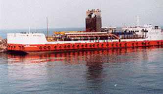
to operate an Engineering cycle to produce net power.� The technology
can be housed either in a ship (left) or within an onshore plant with
pipes which reach out to sea taking the hot and cold waters required
for operation.
Ocean
Thermal Energy Conversion (OTEC) is an energy technology that converts
solar radiation absorbed by the oceans to electrical power. The oceans
cover approximately two thirds of the Earth�s surface, making them
the world�s largest solar energy collector and energy storage system.
On an average day the tropical oceans absorb an amount of solar radiation
equal to about 250 million barrels of oil. If 0.5% of this was converted
into electrical power it would supply the amount of electricity consumed
by the United States on a typical day. This gives an idea of the size
of the resource available to OTEC technology. The principle operation
of the technology utilises the temperature gradient available between
the warm tropical surface water and the cold deep ocean water that
exists at depths of up to 1000m. This temperature gradient is sufficient
to operate an Engineering cycle to produce net power.� The technology
can be housed either in a ship (left) or within an onshore plant with
pipes which reach out to sea taking the hot and cold waters required
for operation.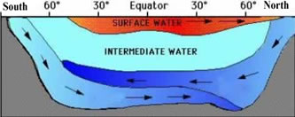 The temperature difference arises from high-density cold water at
the poles sinking and flowing along the seabed to the equatorial areas as
shown (right). The tropical regions of the world have the warmest
surface waters. This is because firstly these areas are closest to
the sun receiving the highest intensity of solar radiation and secondly
because the angle at which sun hits the earth in this region gives
rise to maximum absorption of sunlight and conversion of solar energy
to heat. This second point is easily understood by considering the
intense illumination provided by a flash light facing a surface as
compared to one angled at a surface which will result in more spread
and less intense illumination.
The temperature difference arises from high-density cold water at
the poles sinking and flowing along the seabed to the equatorial areas as
shown (right). The tropical regions of the world have the warmest
surface waters. This is because firstly these areas are closest to
the sun receiving the highest intensity of solar radiation and secondly
because the angle at which sun hits the earth in this region gives
rise to maximum absorption of sunlight and conversion of solar energy
to heat. This second point is easily understood by considering the
intense illumination provided by a flash light facing a surface as
compared to one angled at a surface which will result in more spread
and less intense illumination. As
a result, between latitudes of around 20o north and south,
the thermal structure of the oceans represents a temperature difference
of around 22oK between the surface at around 26oC,
and 4oC water at depths of around 1000m. Variations in
the extremes of hot and cold occur in different areas. The thermocline
shown to the left represents the major thermal gradient that exists.
Between depths of 1000m and 5000m the rate of change of the temperature
is only a few tenths of a degree per kilometre
As
a result, between latitudes of around 20o north and south,
the thermal structure of the oceans represents a temperature difference
of around 22oK between the surface at around 26oC,
and 4oC water at depths of around 1000m. Variations in
the extremes of hot and cold occur in different areas. The thermocline
shown to the left represents the major thermal gradient that exists.
Between depths of 1000m and 5000m the rate of change of the temperature
is only a few tenths of a degree per kilometre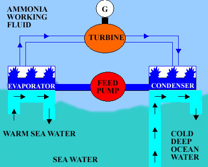 Ammonia
is more volatile, than for example water, and so it is possible to
evaporate this liquid in a closed system to a saturated vapour at
a higher pressure by heat transfer from warm tropical surface waters
in a heat exchanger. This ammonia vapour then expands through a purpose
built turbine, which directly produces mechanical power like any conventional
steam cycle system. The ammonia vapour then needs to be condensed
back to a liquid to complete the cyclic process and this is achieved
by cooling the ammonia vapour with cold deep ocean water from 1000m
(4oC). This deep ocean source of cold water is pumped up
to the surface in order to cool the working fluid (ammonia) back to
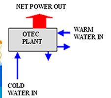
a liquid so that it may then be pumped back to the evaporator. The
gross power from the turbine drives a generator, which supplies power
to the various pumps. The remaining electricity is known as the Net
Power. The total pumping power can be up to two thirds of the total
generation since very large flow rates are required. A simple schematic
of the cyclic process is outlined (right) for the closed cycle system.
Other cycles exist including the open cycle and hybrid cycles that
use water or a combination of water and ammonia as the working fluids.
These cycles offer additional benefits to certain environments including
the production of fresh water. An account of established technology
is given later in this page.
Ammonia
is more volatile, than for example water, and so it is possible to
evaporate this liquid in a closed system to a saturated vapour at
a higher pressure by heat transfer from warm tropical surface waters
in a heat exchanger. This ammonia vapour then expands through a purpose
built turbine, which directly produces mechanical power like any conventional
steam cycle system. The ammonia vapour then needs to be condensed
back to a liquid to complete the cyclic process and this is achieved
by cooling the ammonia vapour with cold deep ocean water from 1000m
(4oC). This deep ocean source of cold water is pumped up
to the surface in order to cool the working fluid (ammonia) back to
a liquid so that it may then be pumped back to the evaporator. The
gross power from the turbine drives a generator, which supplies power
to the various pumps. The remaining electricity is known as the Net
Power. The total pumping power can be up to two thirds of the total
generation since very large flow rates are required. A simple schematic
of the cyclic process is outlined (right) for the closed cycle system.
Other cycles exist including the open cycle and hybrid cycles that
use water or a combination of water and ammonia as the working fluids.
These cycles offer additional benefits to certain environments including
the production of fresh water. An account of established technology
is given later in this page. 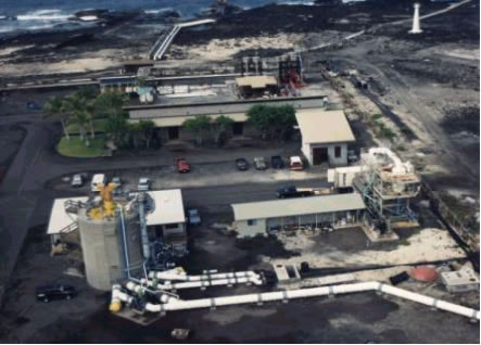 The
invention of the Kalina cycle heralded a new era by providing
far higher efficiencies than the conventional Rankine Cycle.
Subsequently, in 1994, Japanese physicist Dr. H. Uehara invented
a more advanced cycle. This cycle known as the �Uehara Cycle�
reduces the load on the condenser thus paving way for a possible
compact sized OTEC plant with efficiencies higher than the Kalina
Cycle, that took the cycle technology a step forward towards
the goal of commercialisation. The research and development
of OTEC has been pioneered by a handful of Institutes around
the world. Prominent among them are NELHA (Natural Energy Laboratory
of Hawaii Authority), Hawaii, Xenesys Inc and Saga University
of Japan, NIOT (National Institute of Ocean Technology) India,
NREL (National Renewable Energy Laboratory), USA. However, there
have not been many OTEC plants around the globe because either
the technology was not available for low-grade heat conversion
applications or the costs were so prohibitive that it was almost
impossible to design and conceive a plant. Nevertheless, a few
demonstration plants have been set up in some parts of the world
for example in Hawaii and India.� These demonstration plants
serve the dual purpose of design testing and evaluation and
also could garner credible data that can be used for future
real scale applications. Besides, the experience of demonstration
plants over a period can give a deep insight into the real time
Operation and Maintenance problems One such plant that was built
during the last decade was a 210 KW experimental� plant completed
in Hawaii in 1993. This was built based on the Open Cycle under
the sponsorship of the U.S. Department of Energy, which was
often referred to as NPPE (Net Power Producing Experiment).�
The
invention of the Kalina cycle heralded a new era by providing
far higher efficiencies than the conventional Rankine Cycle.
Subsequently, in 1994, Japanese physicist Dr. H. Uehara invented
a more advanced cycle. This cycle known as the �Uehara Cycle�
reduces the load on the condenser thus paving way for a possible
compact sized OTEC plant with efficiencies higher than the Kalina
Cycle, that took the cycle technology a step forward towards
the goal of commercialisation. The research and development
of OTEC has been pioneered by a handful of Institutes around
the world. Prominent among them are NELHA (Natural Energy Laboratory
of Hawaii Authority), Hawaii, Xenesys Inc and Saga University
of Japan, NIOT (National Institute of Ocean Technology) India,
NREL (National Renewable Energy Laboratory), USA. However, there
have not been many OTEC plants around the globe because either
the technology was not available for low-grade heat conversion
applications or the costs were so prohibitive that it was almost
impossible to design and conceive a plant. Nevertheless, a few
demonstration plants have been set up in some parts of the world
for example in Hawaii and India.� These demonstration plants
serve the dual purpose of design testing and evaluation and
also could garner credible data that can be used for future
real scale applications. Besides, the experience of demonstration
plants over a period can give a deep insight into the real time
Operation and Maintenance problems One such plant that was built
during the last decade was a 210 KW experimental� plant completed
in Hawaii in 1993. This was built based on the Open Cycle under
the sponsorship of the U.S. Department of Energy, which was
often referred to as NPPE (Net Power Producing Experiment).�
 The
next demonstration project to follow was a 1MW barge mounted
Indian OTEC
The
next demonstration project to follow was a 1MW barge mounted
Indian OTEC project built in the year 2001�and pioneered by NIOT, Chennai.
This is the largest ever built OTEC Plant. This is based on
closed cycle with Ammonia as working fluid. This plant has showcased
the state of art technologies available for closed cycle OTEC
applications. Compact plate type heat exchangers are used for
both the evaporator and the condenser. Other system components
include a 4-stage axial flow reaction turbine coupled with a
synchronous generator through a 2:1 reduction gearbox. For a
considerable range of pressure ratios, the turbine efficiency
remains above 85%. The sea water system comprises a cold water
pipe, a warm water pipe, a mixed discharge pipe and ducting
mounted on a non-self propelled barge. The cold water pipe is
made of High-Density Polyethylene and is of 1 meter in diameter.
A surface buoy, hanger, anchor lines and the anchor form other
components of the Single Point Mooring.
project built in the year 2001�and pioneered by NIOT, Chennai.
This is the largest ever built OTEC Plant. This is based on
closed cycle with Ammonia as working fluid. This plant has showcased
the state of art technologies available for closed cycle OTEC
applications. Compact plate type heat exchangers are used for
both the evaporator and the condenser. Other system components
include a 4-stage axial flow reaction turbine coupled with a
synchronous generator through a 2:1 reduction gearbox. For a
considerable range of pressure ratios, the turbine efficiency
remains above 85%. The sea water system comprises a cold water
pipe, a warm water pipe, a mixed discharge pipe and ducting
mounted on a non-self propelled barge. The cold water pipe is
made of High-Density Polyethylene and is of 1 meter in diameter.
A surface buoy, hanger, anchor lines and the anchor form other
components of the Single Point Mooring.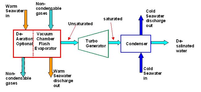 The
open cycle OTEC uses the warm surface water itself as the waorking
fluid. The water vaporizes in a near vacuum at surface water temperatures.
The expanding vapour drives a low pressure turbine attached to
a generator which produces electricity. The vapour, which has
lost its salt and is almost pure fresh water , is condensed back
into a liquid by exposure to cold temperatures from deep ocean
water. If the condenserkeeps teh vapour from direct contact with
the sea water, the condensed water can be used for fresh water
(desalinated) for drinking or agriculture. With a direct contact
condenser it is possible to produce more electricity, but the
vapour is mixed with the cooloing water and discharged back into
the ocean. The process is repeated with a continuous supply of
warm surface water.
The
open cycle OTEC uses the warm surface water itself as the waorking
fluid. The water vaporizes in a near vacuum at surface water temperatures.
The expanding vapour drives a low pressure turbine attached to
a generator which produces electricity. The vapour, which has
lost its salt and is almost pure fresh water , is condensed back
into a liquid by exposure to cold temperatures from deep ocean
water. If the condenserkeeps teh vapour from direct contact with
the sea water, the condensed water can be used for fresh water
(desalinated) for drinking or agriculture. With a direct contact
condenser it is possible to produce more electricity, but the
vapour is mixed with the cooloing water and discharged back into
the ocean. The process is repeated with a continuous supply of
warm surface water. In
the Closed-cycle system, heat transferred from the warm surface
seawater causes a working fluid (such as ammonia, Freon, or propane)
to turn to vapour. The expanding vapour drives a turbine attached
to a generator, which produces electricity. Cold seawater passing
through a condenser containing the vaporised working fluid turns
the vapour back into a liquid, which is then recycled through
the system.
In
the Closed-cycle system, heat transferred from the warm surface
seawater causes a working fluid (such as ammonia, Freon, or propane)
to turn to vapour. The expanding vapour drives a turbine attached
to a generator, which produces electricity. Cold seawater passing
through a condenser containing the vaporised working fluid turns
the vapour back into a liquid, which is then recycled through
the system.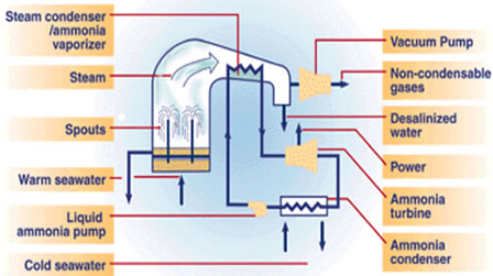 Though
named Hybrid Cycle, the working fluid that turns the turbine
circulates in a closed loop and hence categorised under closed
cycle. In essence, it combines the advantages of both Open Cycle
and Closed Cycle systems to optimise production of electricity
and fresh water.
Though
named Hybrid Cycle, the working fluid that turns the turbine
circulates in a closed loop and hence categorised under closed
cycle. In essence, it combines the advantages of both Open Cycle
and Closed Cycle systems to optimise production of electricity
and fresh water. 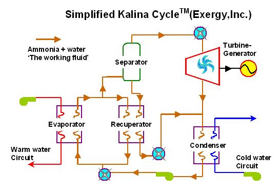 This
is a variation of conventional closed cycle system using ammonia-water
mixture as working fluid in place of conventional ammonia. This
system provides 80% higher efficiency than conventional closed
cycles. It has the flexibility of changing the ammonia-water
concentrations for optimisation based on system temperatures.
The additional component recuperator minimises heat losses through
heat recovery process. Since working fluid is aqueous ammonia,
the cold water temperature can be higher than that required
for othher cycles, thus reducing the length and thereby costs
of cold water piping.
This
is a variation of conventional closed cycle system using ammonia-water
mixture as working fluid in place of conventional ammonia. This
system provides 80% higher efficiency than conventional closed
cycles. It has the flexibility of changing the ammonia-water
concentrations for optimisation based on system temperatures.
The additional component recuperator minimises heat losses through
heat recovery process. Since working fluid is aqueous ammonia,
the cold water temperature can be higher than that required
for othher cycles, thus reducing the length and thereby costs
of cold water piping. The
fluid, made up of an ammonia/water mixture, is sent through
a regenerator by a working fluid pump to the evaporator. The
warm seawater from the surface layer of the ocean is pumped
into the evaporator through a warm seawater pump. This vaporizes
the ammonia/water fluid into ammonia/water vapor, which is a
saturated vapor, so in the separator it separates into aqueous
ammonia and ammonia/water vapor. The ammonia/water vapor passes
through the first turbine, spinning the turbine to produce electricity.
After going through the turbine, part of the vapor mixture is
extracted and sent to a heater, while the remainder goes through
the second turbine, which spins a generator to produce electricity.
The
fluid, made up of an ammonia/water mixture, is sent through
a regenerator by a working fluid pump to the evaporator. The
warm seawater from the surface layer of the ocean is pumped
into the evaporator through a warm seawater pump. This vaporizes
the ammonia/water fluid into ammonia/water vapor, which is a
saturated vapor, so in the separator it separates into aqueous
ammonia and ammonia/water vapor. The ammonia/water vapor passes
through the first turbine, spinning the turbine to produce electricity.
After going through the turbine, part of the vapor mixture is
extracted and sent to a heater, while the remainder goes through
the second turbine, which spins a generator to produce electricity.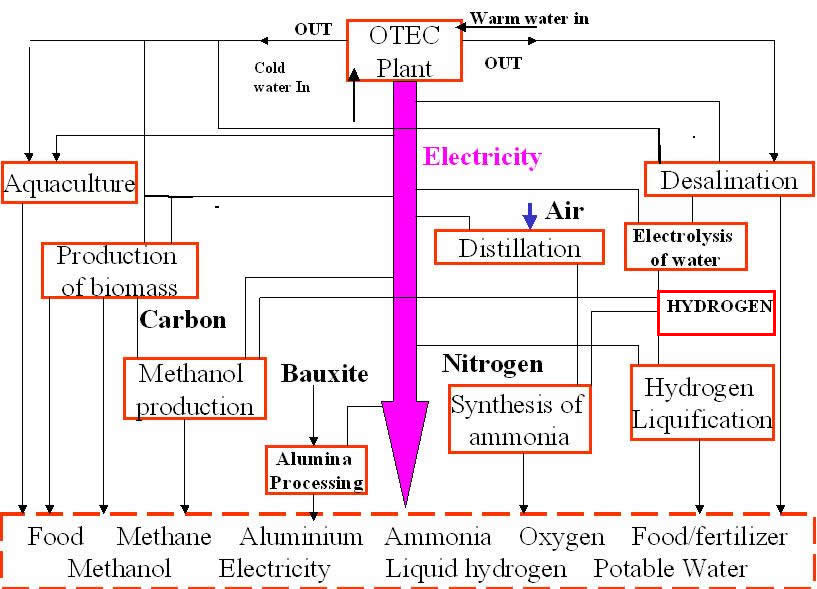 The flow diagaram below illustrates some of the potential products.
Since OTEC is not yet commercially viable this diagram represents
some time in the future. The main pink arrow represents electrical
power production however using this directly for domestic power
will not always be the most practical option and as illustrated
there are many options for fuel production (eg Hydrogen or Methanol)
or indirect synthesis of certain major chemical feedstocks which
could then be used or transported to areas of demand as an export.
Many future OTEC facilities will likely be on ships grazing
tropical waters. Since storage of large amounts of electrical
energy is not possible and cable transmission to shore is not
a practical option it is likely that these plant ships will
produce chemicals with the electrical power generated.
The flow diagaram below illustrates some of the potential products.
Since OTEC is not yet commercially viable this diagram represents
some time in the future. The main pink arrow represents electrical
power production however using this directly for domestic power
will not always be the most practical option and as illustrated
there are many options for fuel production (eg Hydrogen or Methanol)
or indirect synthesis of certain major chemical feedstocks which
could then be used or transported to areas of demand as an export.
Many future OTEC facilities will likely be on ships grazing
tropical waters. Since storage of large amounts of electrical
energy is not possible and cable transmission to shore is not
a practical option it is likely that these plant ships will
produce chemicals with the electrical power generated. 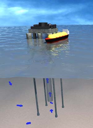
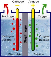 Many
researchers involved in OTEC have visualised permanent platforms
which will continually produce Hydrogen by electrolysis (passing
electric currrent through water producing oxygen and hydrogen
at the two electrodes as shown (right))and then liquefy it in
tanks for callection by tanker ships. This could well be an
element of a future hydrogen economy. The offshore technology
is well establised and the set up would not be dissimilar to
offshore oil operations that exist today. Platforms would be
constructed and from these deep ocean water pipes would descend
to below 1000m (left) to obtain the requried cold water. Large
tanker ships would travel from platform to platform callecting
the liquid hydrogen fuel which would then be shiped ashore for
use as an automotive fuel or chemical feedstock.
Many
researchers involved in OTEC have visualised permanent platforms
which will continually produce Hydrogen by electrolysis (passing
electric currrent through water producing oxygen and hydrogen
at the two electrodes as shown (right))and then liquefy it in
tanks for callection by tanker ships. This could well be an
element of a future hydrogen economy. The offshore technology
is well establised and the set up would not be dissimilar to
offshore oil operations that exist today. Platforms would be
constructed and from these deep ocean water pipes would descend
to below 1000m (left) to obtain the requried cold water. Large
tanker ships would travel from platform to platform callecting
the liquid hydrogen fuel which would then be shiped ashore for
use as an automotive fuel or chemical feedstock.  Ocean
Thermal Energy Conversion is a clean and renewable source
of energy with the potential to replace a significantfraction
of conventional fossil fuelled power production methods and
in turn assist with the decrease of C02 emissions
to the atmosphere. However like any new development this is
not the whole picture and OTEC does have some environmental
impacts which are highly specific to this technology. These
are discussed below and include: the variation in local ocean
temperatures and currents, nutrient enhancement in surface
layers, chemical pollution, structural effects, fish attraction
and population, accidents and others
Ocean
Thermal Energy Conversion is a clean and renewable source
of energy with the potential to replace a significantfraction
of conventional fossil fuelled power production methods and
in turn assist with the decrease of C02 emissions
to the atmosphere. However like any new development this is
not the whole picture and OTEC does have some environmental
impacts which are highly specific to this technology. These
are discussed below and include: the variation in local ocean
temperatures and currents, nutrient enhancement in surface
layers, chemical pollution, structural effects, fish attraction
and population, accidents and others Deep-sea
water is cold and rich in nutrients such as carbon, nitrate
and phosphate compounds that enhance the growth of marine
life. Any OTEC operation is likely to produce an artificial
upwelling of cold nutrient rich water to the sea surface.
This may alter the natural state of nutrient-poor marine ecosystems
by artificially enriching surface water that it is advantageous
for the marine life. This redistribution of nutrients may
improve fishing within the localised area and enhance growth
of phytoplankton. Fish that are already attracted to structures
are likely to become concentrated in population near OTEC
plants. This artificial upwelling will likely result in artificial
reefs and indeed this technology separate from power production
can be used to regenerate damaged reefs.
Deep-sea
water is cold and rich in nutrients such as carbon, nitrate
and phosphate compounds that enhance the growth of marine
life. Any OTEC operation is likely to produce an artificial
upwelling of cold nutrient rich water to the sea surface.
This may alter the natural state of nutrient-poor marine ecosystems
by artificially enriching surface water that it is advantageous
for the marine life. This redistribution of nutrients may
improve fishing within the localised area and enhance growth
of phytoplankton. Fish that are already attracted to structures
are likely to become concentrated in population near OTEC
plants. This artificial upwelling will likely result in artificial
reefs and indeed this technology separate from power production
can be used to regenerate damaged reefs.
 Entrained
organisms may be exposed to biocides, physical disturbance
(acceleration, impaction, forces and abrasion) and temperature
and pressure shock. The impact of OTEC operations on endangered
species must be evaluated for each site. It is important
to identify transients such as the green sea turtles or
other marine mammals attracted to the warm water intake
and minimise impacts to such species. At this stage in OTEC
development impacts are really minimal since so few projects
exist, however if in the future large areas of ocean are
sourced for this technology impacts will become important.
Entrained
organisms may be exposed to biocides, physical disturbance
(acceleration, impaction, forces and abrasion) and temperature
and pressure shock. The impact of OTEC operations on endangered
species must be evaluated for each site. It is important
to identify transients such as the green sea turtles or
other marine mammals attracted to the warm water intake
and minimise impacts to such species. At this stage in OTEC
development impacts are really minimal since so few projects
exist, however if in the future large areas of ocean are
sourced for this technology impacts will become important.
 The
environmental impacts related to OTEC are relatively benign
and major concerns specific to OTEC are discussed above.
Any real assessment would be site specific and it should
be made clear that EIA will differ for onshore plants and
offshore platforms or vessels. Further considerations include
life cycle emissions for construction operation and decommissioning
and many other considerations that are generic to all major
developments, such as noise pollution, transport of materials
and equipment and creation of access roads. In the case
of OTEC the cold water pipe, which for land based projects,
would require to stretch kilometres out to sea quite and
possibly intrude on sensitive reefs and ecosystems. The
cold water pipe installation is a risky task and consequences
of dropping and sinking a pipe would also need consideration
in EIA. Local climate would also need to be assessed in
any risk assessment since large leaks of working fluid could
be very harmful and could easily occur after storm damage
to vessels or onshore plants.
The
environmental impacts related to OTEC are relatively benign
and major concerns specific to OTEC are discussed above.
Any real assessment would be site specific and it should
be made clear that EIA will differ for onshore plants and
offshore platforms or vessels. Further considerations include
life cycle emissions for construction operation and decommissioning
and many other considerations that are generic to all major
developments, such as noise pollution, transport of materials
and equipment and creation of access roads. In the case
of OTEC the cold water pipe, which for land based projects,
would require to stretch kilometres out to sea quite and
possibly intrude on sensitive reefs and ecosystems. The
cold water pipe installation is a risky task and consequences
of dropping and sinking a pipe would also need consideration
in EIA. Local climate would also need to be assessed in
any risk assessment since large leaks of working fluid could
be very harmful and could easily occur after storm damage
to vessels or onshore plants.