 | The Capture and Sequestration of Carbon Dioxide |
|
 The Technology for Capturing
Carbon Dioxide
 CO2 Capture Methods

 Solvent Absorption (Solvent Scrubbing)

- Physical solvent e.g. Selexol TM
- Based on Henry’s Law (Temperature & Pressure dependent with absorption occurring at low temperature and high pressure)
- Applicable for high CO 2 concentration (CO 2 Partial pressure >525 kPa).
- Chemical solvent e.g. Mono-ethanol amine (MEA)
- Depends on acid base neutralization reaction
- Applicable for low to moderate CO 2 partial pressure (3.5 to 21.0 kPa)
Chemical stripping: -
Chemical absorption is the most suitable method for the separation of CO2 from exhaust gases,
when carbon dioxide has a low concentration (5-15% by volume)
in a gaseous stream at atmospheric pressure.
The separation process of carbon dioxide by chemical absorption consists of two steps:
- The absorption of CO2 by chemical solvents at a low temperature (40-65°C)
- The recovery of CO2 from chemical solvents by using low-grade heat (a temperature in the range of 100-150°C), usually extracted from power plants.
Absorption reaction:
2MEA+CO2 ßà MEACOO-+MEAH+
PCO2 = K [ MEAH+ ][ MEACOO- ] / [ MEA ] 2
=K a 2/(1-2 a ) 2
a =CO2_Loading=Total_CO2/Total_MEA

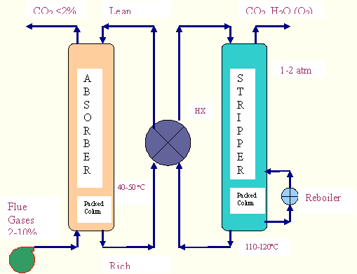
In the MEA process CO2 from the cooled power plant exhaust gas reacts with aqueous solution of MEA in
a contacting device, usually an absorption tower at a
pressure slightly above the ambient pressure and at a temperature depending on the power plant upstream.
First, they are compressed to about 1.3 bars, to
overcome pressure drops within the system, and cooled to nearly 50°C. Then, the gases go to the
absorption column where the carbon dioxide binds to the solvent
chemically. Most of the CO2 is thus removed from the exhaust gas that is released to the atmosphere
and the reach solution (i.e. the solution containing the
absorbed CO2) flows to a lean/rich heat exchanger: here the hot lean solution, coming from the stripper
column (regenerator), cools itself giving out its heat to the
rich solution, which then goes to the regenerator. Here the solvent is regenerated by heat where the
chemical bonds are decomposed thermally. The CO2 and
water vapour leaving the stripper is next cooled and essentially pure CO2 leaves the separation plant
for further treatment (in this case compression and drying).
There are two energy requirements for this process:
- Regeneration heat for the solvent: According to literature the required heat is 4 MJ per kg of recovered carbon dioxide, which is provided by the low pressure steam from the power plant. Assuming the temperature for the regeneration of the solvent about 150°C so that the extraction of the steam takes place at about 5 bars. The steam provides its latent heat of condensation and returns into the power plant as saturated liquid at the same pressure as its extraction. Thus, the amount of steam for the regeneration can be determined by the quantity of CO2 recovered and by the characteristics (temperature and pressure) of the extracted steam.
- Energy for the compression of the flue gases and for the pumping of the amine solution through the removal plant: According to literature, the required energy is 0.11 MJ per kg of CO2 recovered. This amount of energy is subtracted from the total plant work to obtain the network.
The amount of CO2 that can be removed from the exhaust depends on the size of the absorption unit and the concentration of CO2 in the exhaust. For a standard plant the economical recovery limit is approximately 85% for 3% CO2 in the exhaust and 90-92% for 8%.
A key requirement is to limit losses of solvent both as ‘carry-over’ in the flue gas and as heat-stable salts. There are a few facilities in which amines are used to capture CO2 from flue gas streams.
Improved solvents could reduce energy requirement by as much as 40 % compared to conventional MEA solvents. There is considerable interest in the use of sterically hindered amines, which are claimed to have good absorption and desorption characteristics.
Avoiding oxidation:
Following steps can be adapted to control the rate of degradation in the oxidizing environment of a flue gas.
- Minimize contact time with dissolved O2
- Minimize dissolved metals, Nox
- Add chelators or free radical scavengers
- Use solvents that oxidize slower
- Hindered amines with tertiary or quarterly C’s
- Tertiary amines (?)
- K2 CO3
Plant Materials:
- CH4 & H2 Systems use Carbon Steel
- High pressure & capital costs dominate
- Corrosion by loaded solutions and degradation products
- Corrosion inhibitors are effective with CS
- For < 30% MEA, <0.45 loading, small salt concentration
- Metals (Cu+2,V+5) give oxidized Fe2O3 film
- But catalyze degradation
- Corrosion resistant materials of construction
- FRP, SS, lined CS: as in FGD systems
- Cost effective with larger systems at 1 atmosphere
- Relaxes constraints on solvent concentration and CO2 loading


